— Defective gauge assemble, check for the A21
Speed Sensor Input Test
NOTE: Check the No. 2 (15 A) fuse in the under-dash
fuse box, before testing.
1. Disconnect the 3-P connector from the speed sensor.
View from
terminal side
SPEED SENSOR
3-P CONNECTOR
2. Check for continuity between the BLK terminal and
the body ground.
There should be continuity.
If there is no continuity, check for:
— An open in the BLk wire.
— Poor ground (G101)
If there is continuity, go to step 3.
3. Check for vortage between the BLK/YEL terminal and
the body ground with the ignition switch ON.
There should be battery voltage.
If there is no voltage, check for an open in the
BLK/YEL wire.
If there is battery voltage, go to step 4.
4. Check for voltage between the YEL/RED terminal and
body ground with the ignition switch ON.
There should be approximately 5 V.
If there is no voltage, check for:
terminal of the A connector (see page 23-121).
If there are approximately 5 V, go to step 5.
5. If all continuity and voltage tests are normal, but the
speedometer and the odo/trip meter do not operate,
replace the speed sensor.
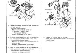
Replacement
1. Disconnect the 3-P connector from the speed sensor.
2. Remove the mounting bolts and the speed sensor,
then take out the speed sensor assembly.
DRIVE LINK
3-P CONNECTOR
3. Install in the reverse order of removal.
NOTE: Be careful not to lose the drive link, because
it is a tiny part.
BLK
YEL/RED
BLK/YEL
SPEED SENSOR
COVER
MOUNTING BOLTS
Speed Sensor Input Test
NOTE: Check the No. 2 (15 A) fuse in the under-dash
fuse box, before testing.
1. Disconnect the 3-P connector from the speed sensor.
View from
terminal side
SPEED SENSOR
3-P CONNECTOR
2. Check for continuity between the BLK terminal and
the body ground.
There should be continuity.
If there is no continuity, check for:
— An open in the BLk wire.
— Poor ground (G101)
If there is continuity, go to step 3.
3. Check for vortage between the BLK/YEL terminal and
the body ground with the ignition switch ON.
There should be battery voltage.
If there is no voltage, check for an open in the
BLK/YEL wire.
If there is battery voltage, go to step 4.
4. Check for voltage between the YEL/RED terminal and
body ground with the ignition switch ON.
There should be approximately 5 V.
If there is no voltage, check for:
terminal of the A connector (see page 23-121).
If there are approximately 5 V, go to step 5.
5. If all continuity and voltage tests are normal, but the
speedometer and the odo/trip meter do not operate,
replace the speed sensor.
Replacement
1. Disconnect the 3-P connector from the speed sensor.
2. Remove the mounting bolts and the speed sensor,
then take out the speed sensor assembly.
DRIVE LINK
3-P CONNECTOR
3. Install in the reverse order of removal.
NOTE: Be careful not to lose the drive link, because
it is a tiny part.
BLK
YEL/RED
BLK/YEL
SPEED SENSOR
COVER
MOUNTING BOLTS