Function Test
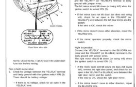
NOTE: Before testing, remove the left door panel, then
disconnect all connectors from the door panel.
10-P CONNECTOR
DOOR PANEL
View from wire side
NOTE: Check the No. 4 (15A) fuse in the under-dash
fuse box before testing.
One or both inoperative:
1. Check for voltage between the YEL/BLK1 terminal
and body ground with the ignition switch ON (II).
There should be battery voltage.
• If there is no voltage, check for an open in the
YEL/BLK1 wire.
• If there is battery voltage, go to step 2.
2. Check for continuity between the BLK terminal and
body ground.
There should be continuity. If there is no continui-
ty, check for:
• An open in the BLK wire.
• Poor ground (G401, G402, G403).
Left inoperative:
Connect the YEL/BLK1 terminal to the YEL/RED terminal
and the YEL/WHT (or YEL/BLK2) terminal to body
ground with jumper wires.
The left mirror should tilt down (or swing left) when the
ignition switch is turned ON (II).
• If the mirror does not tilt down (or does not swing
left), check for an open in the YEL/WHT (or
YEL/BLK2) wire between the left door mirror and the
switch.
If the wire is OK, check the mirror.
• If the mirror doesn’t move either direction, repair the
YEL/RED wire.
• If the mirror operates properly, check the mirror
switch.
Right inoperative:
Connect the YEL/BLK1 terminal to the BLU/GRN ter-
minal and the YEL/WHT (or BLU/BLK) terminal to the
body ground with jumper wires.
The right mirror should tilt down (or swing left) when
the ignition switch is turned ON (II).
• If the mirror does not tilt down (or does not swing
left), remove the right door panel, and check for an
open in the YEL/WHT or BLU/BLK) wire between the
right door mirror and the switch.
If the wire is OK, check the right door mirror.
• If the mirror doesn’t move in either direction, repair
the BLU/GRN wire.
• If the mirror operates properly, check the mirror
switch.