Category: Electrical
Categories
nsxd23154a.pdf
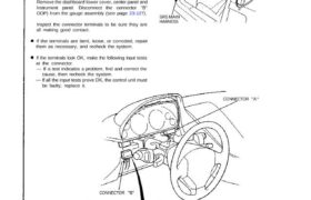
— If all the input tests prove OK, the control unit must CAUTION: All SRS wiring harnesses are covered with yellow out- er insulation. Before disconnecting any part of the SRS wire hap ness, install the short connectors (see page 24-10(’93-’96)) Replace the entire affected SRS harness assembly if it has an open circuit or […]
Categories
nsxb23082a.pdf
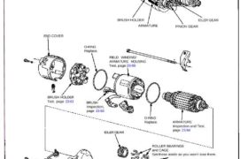
Starting System CAUTION: Disconnect the ground cable from the bat- tery before removing the starter. SOLENOID PLUNGER Inspection, page 23-86 STARTER SOLENOID Test, page 23-81 OVERRUNNING CLUTCH ASSEMBLY BRUSH HOLDER ARMATURE IDLER GEAR PINION GEAR END COVER O-RING Replace. FIELD WINDING/ ARMATURE HOUSING Test, page 23-86 IDLER GEAR SOLENOID HOUSING HARNESS CLIP BRACKET STEEL BALL […]
Categories
nsxb23227a.pdf
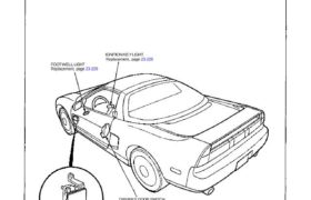
Entry Light Timer System Component Location Index SRS components are located in this area. Review the SRS component locations, precautions, and procedures in the SRS section (24) before performing repairs or service. Description: It the driver’s door has been opened by the outer handle, the foot well light and a light at the Ignition switch […]
Categories
nsxb23298a.pdf
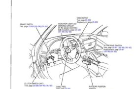
Cruise Control Component Location Index SRS components are located in this area. Review the SRS component locations, precautions, and procedures in the SRS section (24) before performing repairs or ser- vice. BRAKE SWITCH Test, page 23-308 (’93-’96) (’91-’92) INDICATOR LIGHT and DIMMING CIRCUIT (In tha gauge assembly) Bulb Locations, page 23-128 (’94-’96) (’91-’93) MAIN SWITCH […]
Categories
nsxb23235a.pdf
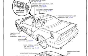
Stereo Sound System Component Location Index SRS components are located in this area. Review the SRS component locations, precautions, and procedures in the SRS section 24 before performing repairs or ser- vice. POWER AMPLIFIER RELAY Test, page 23-240 STEREO RADIO/CASSETTE PLAYER Removal, page 23-238 Terminals, page 23-240 FOOT WELL BASS SPEAKER Replacement, page 23-245 PASSENGER’S […]
Categories
nsxb23267a.pdf
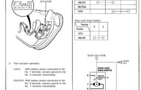
Passenger’s Door Actuator Test – 1. Remove the door panel (see section 20). 2. Disconnect the 8-P connector from the actuator. View from wide side ACTUATOR 3. Test actuator operation: LOCK: With battery power connected to the No. 7 terminal, connect ground to the No. 8 terminal momentarily. UNLOCK: With battery power connected to the […]
Categories
nsxd23303a.pdf
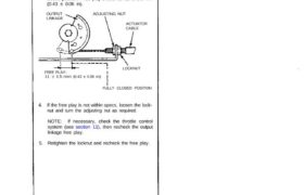
Actuator Cable Adjustment 1. Check that the actuator cable moves smoothly with no binding or sticking. 2. Start the engine and warm it up to normal operating temperature (radiator fan comes on). 3. Measure how far the output linkage moves before the engine speed starts to increase. Make sure you begin with the linkage at […]
Categories
nsxb23285a.pdf
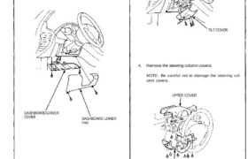
Switch Replacement SRS components are located in this area. Review the SRS component locations, precautions, and procedures in the SRS section 24 before performing repairs or ser- vice. 1. Remove the dashboard lower cover, and disconnect the connectors. 2. Remove the dashboard lower pad. DASHBOARD LOWER COVER DASHBOARD LOWER PAD 3. Remove the tilt cover. […]
Categories
nsxb23234a.pdf
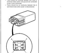
Cigarette Lighter Relay Test 1. Remove the glove box (see section 20). 2. Disconnect the 4-P connector from the cigarette lighter relay (wire colors of 4-P connector: BLU/ GRN, YEL/RED, BRN/YEL, BLK). 3. Check continuity at the relay terminals. • There should be continuity between the C and D terminals. • There should be continuity […]
Categories
nsxb23108a.pdf
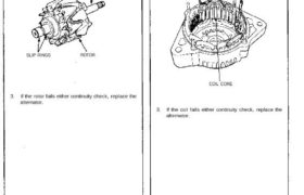
Charging System Rotor Slip Ring Test 1. Check that there is continuity between the slip rings. 2. Check that there is no continuity between the slip rings and the rotor or rotor shaft. ROTOR SHAFT SLIP RINGS ROTOR 3. If the rotor fails either continuity check, replace the alternator. Stator Test 1. Check that there […]