Category: Electrical
Categories
nsxb23181a.pdf
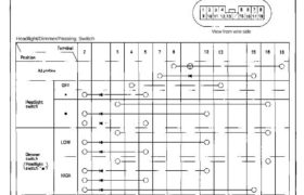
Combination Light/Turn Signal Switch Test 1. Remove the dashboard lower cover (see page 23-182). 2. Disconnect the 18-P connector from the floor wire harness. 3. Check for continuity between the terminals, in each switch position, according to the table. 18-P CONNECTOR View from wire side Turn Signal Switch Headlight/Dimmer/Passing Switch Attachments nsxb23181a (47 kB)
Categories
nsxb23160a.pdf
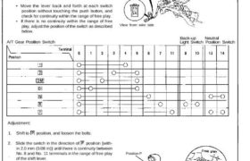
A/T Gear Position Indicator A/T Gear Position Switch Test SRS components are located in this area. Review the SRS component locations, precautions, and procedures in the SRS section 24 before performing repairs or ser- vice. 1. Remove the console, then disconnect the 12-P and 2-P connectors from the A/T gear position switch. 2. Check for […]
Categories
nsxb23320a.pdf
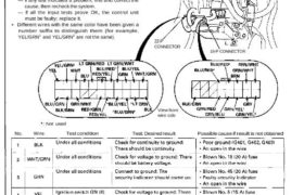
Security Alarm System Control Unit Input Test Remove the glove box, and disconnect the 22-P connec- tor and 16-P connector from the control unit. Inspect the connector and socket terminals to be sure they are all making good contact. • If the terminals are bent, loose, or corroded, repair them as necessary, and recheck the […]
Categories
nsxb23170a.pdf
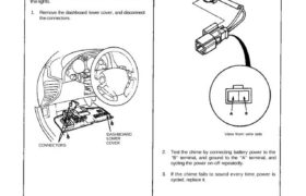
Lights-on Reminder Systen. Chime Test NOTE: Refer to page 23-158 (’93-’96) (’91-’92) for a dia- gram of the lights-on reminder circuit, and page 23-166 for the input test of the circuit. When the ignition key is turned off and removed with the lights on, voltage is applied to the reminder circuit in the integrated control […]
Categories
nsxb23109a.pdf
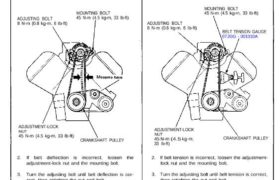
Alternator Belt Adjustment Deflection Method: 1. Apply a force of 100 N (10kg, 22 Ibs) between the alternator and crankshaft pulley, and measure its deflection. Deflection: 11-13.5 mm (0.43-0.53 in) NOTE: On a brand-new belt, the deflection should be 6-8 mm (0.24-0.31 in) before the belt has had any running time on the engine. ADJUSTING […]
Categories
nsxd23070a.pdf
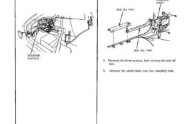
Under-dash Fuse Box CAUTION: All SRS wiring harnesses are covered with yellow outer insulation. Before disconnecting any part of the SRS wire harness, install the short connectors (see page 24-10 (’93-’96)). Replace the entire affected SRS harness assembly if it has an open circuit or damaged wiring. SRS MAIN HARNESS Removal: 1. Disconnect both the […]
Categories
nsxe23251a.pdf
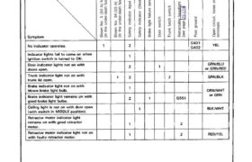
Troubleshooting NOTE: The numbers in the table show the troubleshooting sequence. Main Menu Table of Contents ‚— Troubleshooting NOTE: The numbers in the table show the troubleshooting sequence. Item to be inspected x Б g E fi ‚ч — ь ⊐ f: ä ö 2 б .с ≧ ↼ .D o ∙⊏ .— g ш […]
Categories
nsxb23008a.pdf
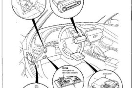
Relay and Control Unit Locations Dashboard TURN SIGNAL/HAZARD RELAY CLIMATE CONTROL UNIT UNDER-DASH FUSE BOX FOOT WELL LIGHT DASHBOARD LOWER COVER INTEGRATED CONTROL UNIT SRS UNIT Attachments nsxb23008a (67 kB)
Categories
nsxd23263a.pdf
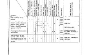
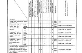
Troubleshooting NOTE: The numbers in the table show the troubleshooting sequence. Item to be inspected Symptom Both windows do not operate. Driver’s window does not operate in any position. Driver’s window does not operate in AUTO. Passenger’s window does not operate. Both windows do not operate within the first ten minutes after the igni- tion […]
Categories
nsxd23150a.pdf
B lo w n N o. 5 ( 1 0 A ) fu se (In t he u nd er -d as h fu se b ox ) B lo w n N o. 3 4 (1 5 A ) fu se (In t he u nd er -d as h fu se b ox […]