Control Unit Input Test
Remove the glove box, and disconnect the 22-P connec-
tor and 16-P connector from the control unit.
Inspect the connector and socket terminals to be sure
they are all making good contact.
• If the terminals are bent, loose, or corroded, repair
them as necessary, and recheck the system.
• If the terminals look OK, make the following input
tests at the connector.
— If any test indicates a problem, find and correct the
cause, then recheck the system.
— If all the input tests prove OK, the control unit
must be faulty; replace it.
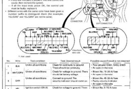
• Different wires with the same color have been given a
number suffix to distinguish them (for example,
YEL/GRN1 and YEL/GRN2 are not the same).
SECURITY
CONTROL UNIT
View from
wire side
Not used
No. Wire Test condition Test: Desired result Possible cause if result is not obtained
22-P
CONNECTOR
16-P CONNECTOR
No. Wire Test condition Test: Desired result Possible cause if result is not obtained
Main Menu
Table of Contents
No. Wire Test condition Test: Desired result Possible cause if result is not obtained
Under all conditions Attach to ground: All horns should ⋅ Blown No. 45 (20 A) fuse
LT GRN/ sound, – Faulty horn relay
7 WHT ∙ Faulty horn (either)
∙ Poor ground (6301 ог G302)
– An open in the wire
Under all conditions Attach to ground: ∙ Faulty headlight relay
8 BLU/RED The headlights should come on. – Faulty headlight system
– An open in the wire
Under all conditions Connect to ground: – Faulty taillight relay
9 RED/VEL The taillights should come on. – Faulty taillight system
– An open in the wire
Passing switch ON Check for voltage to ground: ∙ Faulty passing switch
ю LT GRN/ There should be battery – Faulty dimmer relay
RED voltage. ⋅ Faulty headlight relay
– An open in the wire
Hood open Check for continuity to ground: – Faulty hood switch
П YEUGRNZ There should be continuity. – Misadjusted hood switch
Hood closed Check for continuity to ground: ∎ Poor 9’09″“ (G391)
There should be no continuity. ⋅ An Open ∣∏ the ⋎⋎∣↾≘
ignition key is in the Check for continuity to ground: ⋅ Faulty ignition key switch
ignition switch. There should be continuity. – Poor ground (6401, G402, G403)
12 BLU/GRN ∙ An 0 en in the wìre
Ignition key is not in Check for continuity to ground: p
the ignition switch. There should be no continuity.
Engine compartment Check for continuity to ground: – Faulty engine compartment lid
lid open There should be continuity. switch
13 BLU – Misadjusted engine compart-
Engine compartment Check for continuity to ground: ment lid SWÍtch
lid closed There should be no continuity. ⋅ Poor ground (G401, 6402, G403)
– An open in the wire
BLK/BRN Under all conditions Check for continuity to ground: – Poor ground (G404)
14 or BLK/ There should be continuity. – An open in the wire
LT GRN
Trunk key in UNLOCK Check for continuity to ground: – Faulty trunk key
15 BRNNVHT There should be continuity. – Poor ground (6551)
– An open in the wire
Trunk lid open Check for continuity to ground: – Faulty trunk latch switch
16 WHT There should be continuity. ∙ Misadjusted trunk latch switch
Trunk lid closed
Check for continuity to ground:
There should be no continuity.
– Poor ground (G551)
– An open in the wire
lcont’d)
23-321
Security Alarm System
Control Unit Input Test
View from
wire side
No. Wire Test condition Test: Desired result Possible cause if result is not obtained
NSX-T (open top)