A/T Gear Position Indicator
A/T Gear Position Switch Test
SRS components are located in this area. Review the
SRS component locations, precautions, and procedures
in the SRS section 24 before performing repairs or ser-
vice.
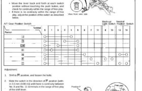
1. Remove the console, then disconnect the 12-P and
2-P connectors from the A/T gear position switch.
2. Check for continuity between the terminals in each
switch position according to the table.
• Move the lever back and forth at each switch
position without touching the push button, and
check for continuity within the range of free play.
• If there is no continuity within the range of free
play, adjust the position of the switch as described
below.
A/T Gear Position Switch
A/T GEAR POSITION SWITCH
View from wire side
Back-up Neutral
Light Switch Position Switch
Adjustment:
1. Shift to position, and loosen the bolts.
2. Slide the switch in the direction of position [with-
in 2.0 mm (0.08 in)] until there is continuity between
No. 8 and No. 11 terminals in the range of free play
of the shift lever.
3. Recheck for continuity between each of the termi-
nals.
NOTE:
• If adjustment is not possible, check for damage
to the shift lever detent and/or bracket. If there is
no damage, replace the A/T gear position switch.
• You should be able to start the engine with the
shift lever in position within the range of free
play.
Position P
LOCK PIN
BOLTS
A/T Gear Position Switch Test
SRS components are located in this area. Review the
SRS component locations, precautions, and procedures
in the SRS section 24 before performing repairs or ser-
vice.
1. Remove the console, then disconnect the 12-P and
2-P connectors from the A/T gear position switch.
2. Check for continuity between the terminals in each
switch position according to the table.
• Move the lever back and forth at each switch
position without touching the push button, and
check for continuity within the range of free play.
• If there is no continuity within the range of free
play, adjust the position of the switch as described
below.
A/T Gear Position Switch
A/T GEAR POSITION SWITCH
View from wire side
Back-up Neutral
Light Switch Position Switch
Adjustment:
1. Shift to position, and loosen the bolts.
2. Slide the switch in the direction of position [with-
in 2.0 mm (0.08 in)] until there is continuity between
No. 8 and No. 11 terminals in the range of free play
of the shift lever.
3. Recheck for continuity between each of the termi-
nals.
NOTE:
• If adjustment is not possible, check for damage
to the shift lever detent and/or bracket. If there is
no damage, replace the A/T gear position switch.
• You should be able to start the engine with the
shift lever in position within the range of free
play.
Position P
LOCK PIN
BOLTS