Security Alarm System
Ignition Key Switch Test
SRS components are located in this area. Review the
SRS component locations, precautions, and procedures
in the SRS section 24 before performing repairs or ser-
vice.
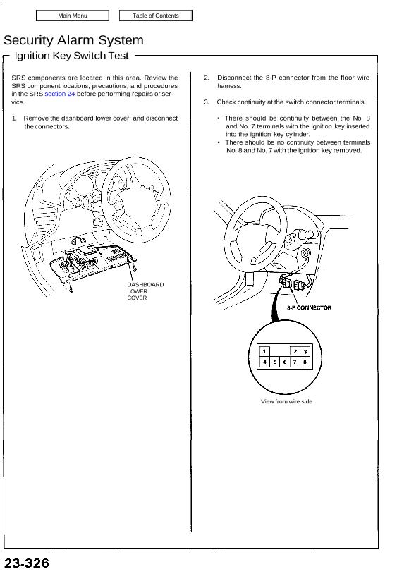
1. Remove the dashboard lower cover, and disconnect
the connectors.
DASHBOARD
LOWER
COVER
2. Disconnect the 8-P connector from the floor wire
harness.
3. Check continuity at the switch connector terminals.
• There should be continuity between the No. 8
and No. 7 terminals with the ignition key inserted
into the ignition key cylinder.
• There should be no continuity between terminals
No. 8 and No. 7 with the ignition key removed.
View from wire side
