Fuel Supply System
Fuel Pump
Description
Because of its compact impeller design, the fuel pump is installed inside the fuel tank, thereby saving space and simplifying the
fuel line system.
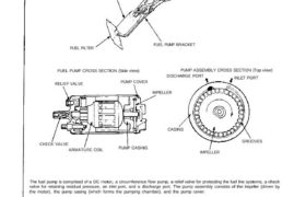
FUEL PUMP
FUEL FILTER
FUEL PUMP BRACKET
FUEL PUMP CROSS SECTION (Side view) PUMP ASSEMBLY CROSS SECTION (Top view)
DISCHARGE PORT INLET PORT
RELIEF VALVE PUMP COVER
IMPELLER
CASING
IMPELLER
GROOVES
PUMP CASINGARMATURE COIL
CHECK VALVE
The fuel pump is comprised of a DC motor, a circumference flow pump, a relief valve for protecting the fuel line systems, a check
valve for retaining residual pressure, an inlet port, and a discharge port. The pump assembly consists of the impeller (driven by
the motor), the pump casing (which forms the pumping chamber), and the pump cover.
OPERATION
(1) When the engine is started, the main relay actuates the pump, and the motor turns together with the impeller.
Differential pressure is generated by the numerous grooves around the impeller.
(2) Fuel entering the inlet port flows inside the motor from the pumping chamber and is forced through the discharge port via
the check valve.
If fuel flow is obstructed at the discharge side of the fuel line, the relief valve will open to bypass the fuel to the inlet port
and prevent excessive fuel pressure.
(3) When the engine stops, the pump stops automatically. However, a check valve closes by spring action to retain the residual
pressure in the line, helping the engine to restart more easily.
Fuel Pump
Description
Because of its compact impeller design, the fuel pump is installed inside the fuel tank, thereby saving space and simplifying the
fuel line system.
FUEL PUMP
FUEL FILTER
FUEL PUMP BRACKET
FUEL PUMP CROSS SECTION (Side view) PUMP ASSEMBLY CROSS SECTION (Top view)
DISCHARGE PORT INLET PORT
RELIEF VALVE PUMP COVER
IMPELLER
CASING
IMPELLER
GROOVES
PUMP CASINGARMATURE COIL
CHECK VALVE
The fuel pump is comprised of a DC motor, a circumference flow pump, a relief valve for protecting the fuel line systems, a check
valve for retaining residual pressure, an inlet port, and a discharge port. The pump assembly consists of the impeller (driven by
the motor), the pump casing (which forms the pumping chamber), and the pump cover.
OPERATION
(1) When the engine is started, the main relay actuates the pump, and the motor turns together with the impeller.
Differential pressure is generated by the numerous grooves around the impeller.
(2) Fuel entering the inlet port flows inside the motor from the pumping chamber and is forced through the discharge port via
the check valve.
If fuel flow is obstructed at the discharge side of the fuel line, the relief valve will open to bypass the fuel to the inlet port
and prevent excessive fuel pressure.
(3) When the engine stops, the pump stops automatically. However, a check valve closes by spring action to retain the residual
pressure in the line, helping the engine to restart more easily.