Steering Column
Inspection
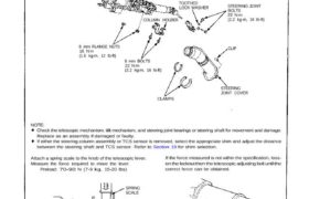
STEERING COLUMN
ASSEMBLY
8 mm FLANGE NUTS
16 N·m
(1.6 kg-m, 12 Ib-ft)
8 mm BOLTS
22 N·m
(2.2 kg-m, 16 Ib-ft)
CLAMPS
STEERING
JOINT COVER
NOTE:
Check the telescopic mechanism, tilt mechanism, and steering joint bearings or steering shaft for movement and damage.
Replace as an assembly if damaged or faulty.
If either the steering column assembly or TCS sensor is removed, select the appropriate shim and adjust the distance
between the steering shaft and TCS sensor. Refer to Section 19 for shim selection.
Attach a spring scale to the knob of the telescopic lever.
Measure the force required to move the lever.
Preload: 70-90 N (7-9 kg, 15-20 Ibs)
If the force measured is not within the specification, loos-
en the locknut then the telescopic adjusting bolt until the
correct force can be obtained.
SPRING
SCALE
TELESCOPIC LEVER
SHIM 6 mm SOCKET BOLT10 N·m
(1.0 kg-m,7 Ib-ft)
TCS SENSOR
COLUMN HOLDER
TOOTHED
LOCK WASHER
CLIP
STEERING JOINT
BOLTS
22 N·m
(2.2 kg-m, 16 Ib-ft)
LOCKNUT
TELESCOPIC
ADJUSTING BOLT
RETAINING
COLLARS
Check for damage.
Inspection
STEERING COLUMN
ASSEMBLY
8 mm FLANGE NUTS
16 N·m
(1.6 kg-m, 12 Ib-ft)
8 mm BOLTS
22 N·m
(2.2 kg-m, 16 Ib-ft)
CLAMPS
STEERING
JOINT COVER
NOTE:
Check the telescopic mechanism, tilt mechanism, and steering joint bearings or steering shaft for movement and damage.
Replace as an assembly if damaged or faulty.
If either the steering column assembly or TCS sensor is removed, select the appropriate shim and adjust the distance
between the steering shaft and TCS sensor. Refer to Section 19 for shim selection.
Attach a spring scale to the knob of the telescopic lever.
Measure the force required to move the lever.
Preload: 70-90 N (7-9 kg, 15-20 Ibs)
If the force measured is not within the specification, loos-
en the locknut then the telescopic adjusting bolt until the
correct force can be obtained.
SPRING
SCALE
TELESCOPIC LEVER
SHIM 6 mm SOCKET BOLT10 N·m
(1.0 kg-m,7 Ib-ft)
TCS SENSOR
COLUMN HOLDER
TOOTHED
LOCK WASHER
CLIP
STEERING JOINT
BOLTS
22 N·m
(2.2 kg-m, 16 Ib-ft)
LOCKNUT
TELESCOPIC
ADJUSTING BOLT
RETAINING
COLLARS
Check for damage.