Removal
1. Remove the rear wheel and bearing unit assembly
(page 18-31).
2. Remove the splash guard from the knuckle.
SPLASH GUARD
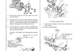
3. Remove the cotter pin from the castle nut of the
toe control arm.
4. Install the 10 mm hex nut on the ball joint. Be sure
that the 10 mm hex nut is flush with the ball joint
pin end, or the threaded section of the ball joint pin
might be damaged by the ball joint remover.
5. Use the ball joint remover, 07MAC – SL00200 (28
mm), as shown on page 18 -21 to separate the ball
joint and toe control arm.
CAUTION: Be careful not to damage the ball joint
boot.
CASTLE NUT 10 x 1.25 mm
44 N·m
(4.4 kg-m, 32 Ib-ft)
COTTER PIN
Replace.
On reassembly,
bend the cotter pin as shown.
BALL JOINT REMOVER, 28 mm
07MAC-SL00200
TOE CONTROL ARM
Corrosion resistant bolt/nut
STABILIZER
LINK
SELF-LOCKING NUT
12 x 1.25 mm
Replace.
85 N·m
(8.5 kg-m, 61 Ib-ft)
REAR
DAMPER
Corrosion resistant bolt/nut
7. Remove the stabilizer link from the stabilizer bar
and knuckle.
Corrosion resistant bolt/nut
Hold.
DAMPER MOUNTING
NUT
12 x 1.25 mm
Replace
95 N·m
(9.5 kg-m,
67 Ib-ft)
6. Hold the stabilizer link with the wrench and remove
the damper mounting nut.
8. Remove the cotter pin from the castle nut of the
lower control arm ball joint and remove the nut.
9. Install the 12 mm hex nut on the ball joint. Be sure
that the 12 mm hex nut is flush with the ball joint
pin end, or the threaded section of the ball joint pin
might be damaged by the ball joint remover.
10. Use the ball joint remover, 07MAC-SL00100 (32
mm), as shown on page 18-21 to separate the ball
joint and lower control arm.
CAUTION: Avoid damaging the ball joint boot.
BALL JOINT
REMOVER, 32 mm
07MAC-SL00100
CASTLE NUT 12 x 1.25 mm
60 N.m
(6.0 kg-m, 43 Ib-ft)
COTTER PIN
Replace.
On reassembly,
bend the cotter
pin as shown.
Corrosion resistant bolt/nut
11. Remove the cotter pin from the castle nut of the
upper control arm ball joint and remove the nut.
12. Install the 12 mm hex nut on the ball joint. Be sure
that the 12 mm hex nut is flush with the ball joint
pin end, or the threaded section of the ball joint pin
might be damaged by the ball joint remover.
13. Use the ball joint remover, 07MAC—SL00100 (32
mm), as shown on page 18-21 to separate the ball
joint and upper control arm.
CAUTION: Avoid damaging the ball joint boot.
BALL JOINT REMOVER. 32 mm
07MAC-SL00100
COTTER PIN
Replace.
On reassembly
bend the cotter
pin as shown.
CASTLE NUT
12 x 1.25 mm
60N.m
(6.0 kg-m, 43 Ib-ft)
Corrosion resistant bolt/nut (cont’d)
REAR
KNUCKLE
1 5. Remove the knuckle assembly from the lower con-
trol arm.
NOTE: Tie plastic bags over the driveshaft ends.
UPPER ARM
14. Separate the knuckle from the upper control arm
and driveshaft outboard joint.
NOTE: Do not remove the driveshafts from the dif-
ferential case or intermediate shaft.
Knuckle/Control Arms
Removal (cont’d)
16. Remove the lower control arm by removing the ad-
just bolt and flange bolt.
* Corrosion resistant bolt/nut SELF-LOCKING NUT14 x 1.5 mm
Replace.
125 N·m
(12.5 kg-m, 90 Ib-ft)
ADJUSTING
CAM
SELF-LOCKING NUT
14 x 1.5 mm
Replace.
125 N·m (12.5 kg-m. 90 Ib-ft)
LOWER CONTROL ARM
ASSEMBLY
17. Remove the upper control arm by removing the
flange bolts.
UPPER CONTROL ARM
ASSEMBLY
*FLANGE BOLT
10 x 1.25 mm
60N·m
(6.0 kg-m, 43 Ib-ft)
* Corrosion resistant bolt/nut
CAUTION: Make sure that the reference marks on
the toe control arm are aligned.
TOE CONTROL ARM ASSEMBLY
FLANGE BOLT
12 x 1.25 mm
95 N·m
(9.5 kg-m. 69 Ib-ft)
18. Remove the toe control arm.