Cruise Control
Main Switch Removal
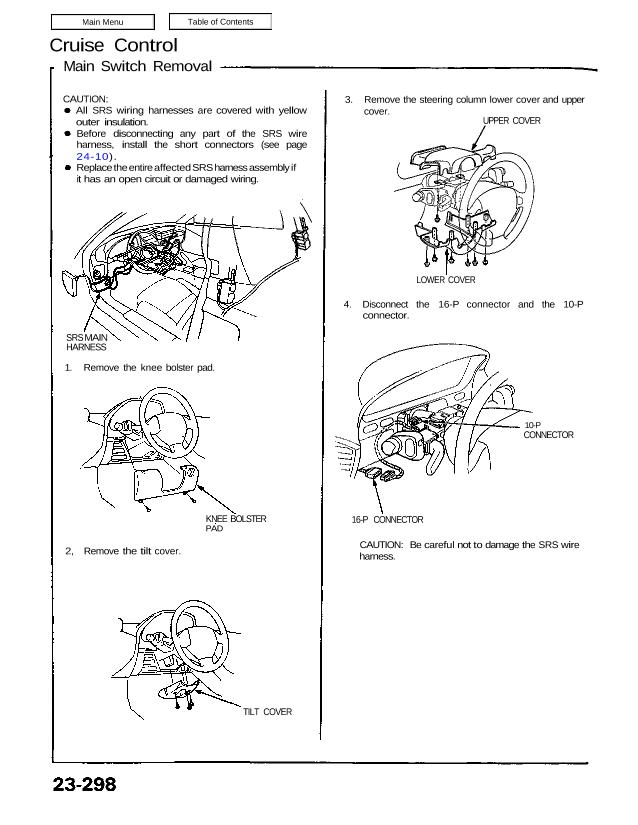
CAUTION:
All SRS wiring harnesses are covered with yellow
outer insulation.
Before disconnecting any part of the SRS wire
harness, install the short connectors (see page
24-10).
Replace the entire affected SRS harness assembly if
it has an open circuit or damaged wiring.
SRS MAIN
HARNESS
1. Remove the knee bolster pad.
KNEE BOLSTER
PAD
2, Remove the tilt cover.
TILT COVER
3. Remove the steering column lower cover and upper
cover.
UPPER COVER
LOWER COVER
4. Disconnect the 16-P connector and the 10-P
connector.
10-P
CONNECTOR
16-P CONNECTOR
CAUTION: Be careful not to damage the SRS wire
harness.
Main Switch Removal
CAUTION:
All SRS wiring harnesses are covered with yellow
outer insulation.
Before disconnecting any part of the SRS wire
harness, install the short connectors (see page
24-10).
Replace the entire affected SRS harness assembly if
it has an open circuit or damaged wiring.
SRS MAIN
HARNESS
1. Remove the knee bolster pad.
KNEE BOLSTER
PAD
2, Remove the tilt cover.
TILT COVER
3. Remove the steering column lower cover and upper
cover.
UPPER COVER
LOWER COVER
4. Disconnect the 16-P connector and the 10-P
connector.
10-P
CONNECTOR
16-P CONNECTOR
CAUTION: Be careful not to damage the SRS wire
harness.
5. Remove the four screws and remove the combina-
tion light switch (main switch).
COMBINATION LIGHT SWITCH
10-P CONNECTOR
16-P CONNECTOR
Main Switch Test
1. Remove the dashboard lower panel and knee
bolster pad.
2. If necessary, remove the knee bolster.
3. Disconnect the 16-P connector and check for con-
tinuity between the terminals in each switch posi-
tion according to the table.
CRUISE
MAIN
SWITCH
16-P CONNECTOR
View from terminal side