Side Marker/Turn Signal/Hazard Flash System
Turn Signal/Hazard Relay Input Test
1. Remove the dashboard lower cover. Remove the turn
signal/hazard relay from the left kick panel, then dis-
connect the 6-P connector.
2. Inspect the connector terminals to be sure they are
all making good contact.
If the terminals are bent, loose or corroded, repair
them as necessary, and recheck the system.
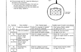
If the terminals look OK, make the following in-
put tests at the connector.
If any test indicates a problem, find and cor-
rect the cause, then recheck the system.
If all the input tests prove OK, the control unit
must be faulty; replace it.
View from
wire side
TURN/SIGNAL
HAZARD RELAY
1
2
3
4
5
6
B
(RED/WHT)
SR
(BLU/YEL)
SL
(BLU/GRN)
SR
(BLU/YEL)
SL
(BLU/GRN)
LR
(GRN/YEL)
LL
(GRN/BLU)
Test condition
Under all conditions.
Ignition switch ON
and turn signal
switch in right
position.
Ignition switch ON
and turn signal
switch in left
position.
Connect the B termi-
nal to the LR
terminal.
Connect the B termi-
nal to the LL
terminal.
Test: Desired result
Check for continuity to ground:
There should be continuity.
Check for voltage to ground:
There should be battery voltage.
Check for voltage to ground:
There should be battery voltage.
Check for voltage to ground:
There should be battery voltage.
Right turn signal lights should come
on.
Left turn signal lights should come
on.
Possible cause if result is not obtained
Poor ground (G401, G402).
An open in the wire.
Blown No. 46 (10 A) fuse.
An open in the wire.
Blown No. 5 (10 A) fuse.
Faulty turn signal switch or cancel
unit.
An open in the wire.
Faulty hazard warning switch.
An open in the wire.
Blown bulb.
Faulty side marker flasher circuit.
Poor ground (G301, G401, G402,
G551).
An open in the wire.
Blown bulb.
Faulty side marker flasher circuit.
Poor ground (G301, G401, G402,
G551).
An open in the wire.
E
(BLK)
TerminalNo.
Under all conditions.
Hazard warning
switch ON.
Turn Signal/Hazard Relay Input Test
1. Remove the dashboard lower cover. Remove the turn
signal/hazard relay from the left kick panel, then dis-
connect the 6-P connector.
2. Inspect the connector terminals to be sure they are
all making good contact.
If the terminals are bent, loose or corroded, repair
them as necessary, and recheck the system.
If the terminals look OK, make the following in-
put tests at the connector.
If any test indicates a problem, find and cor-
rect the cause, then recheck the system.
If all the input tests prove OK, the control unit
must be faulty; replace it.
View from
wire side
TURN/SIGNAL
HAZARD RELAY
1
2
3
4
5
6
B
(RED/WHT)
SR
(BLU/YEL)
SL
(BLU/GRN)
SR
(BLU/YEL)
SL
(BLU/GRN)
LR
(GRN/YEL)
LL
(GRN/BLU)
Test condition
Under all conditions.
Ignition switch ON
and turn signal
switch in right
position.
Ignition switch ON
and turn signal
switch in left
position.
Connect the B termi-
nal to the LR
terminal.
Connect the B termi-
nal to the LL
terminal.
Test: Desired result
Check for continuity to ground:
There should be continuity.
Check for voltage to ground:
There should be battery voltage.
Check for voltage to ground:
There should be battery voltage.
Check for voltage to ground:
There should be battery voltage.
Right turn signal lights should come
on.
Left turn signal lights should come
on.
Possible cause if result is not obtained
Poor ground (G401, G402).
An open in the wire.
Blown No. 46 (10 A) fuse.
An open in the wire.
Blown No. 5 (10 A) fuse.
Faulty turn signal switch or cancel
unit.
An open in the wire.
Faulty hazard warning switch.
An open in the wire.
Blown bulb.
Faulty side marker flasher circuit.
Poor ground (G301, G401, G402,
G551).
An open in the wire.
Blown bulb.
Faulty side marker flasher circuit.
Poor ground (G301, G401, G402,
G551).
An open in the wire.
E
(BLK)
TerminalNo.
Under all conditions.
Hazard warning
switch ON.