TCS Indicator Light
Temporary Driving Conditions:
1. The TCS indicator light will come on and the control unit memorizes the Diagnostic Trouble Code (DTC) under cer-
tain temporary conditions:
2. If the TCS indicator light does not come back on after correcting the tire or tire pressure problem, the TCS system is
OK.
NOTE: Remove the ABS 2.3 (20 A) fuse for at least 3 seconds to clear the DTC from the TCS control unit memory.
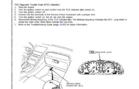
TCS Diagnostic Trouble Code (DTC) Indication:
1. Stop the engine.
2. Turn the ignition switch on and confirm that the TCS indicator light comes on.
3. Turn the ignition switch off.
4. Connect the two terminals of the Service Check Connector with a jumper wire.
5. Turn the ignition switch on, but do not start the engine.
6. Record the blinking frequency of the TCS indicator light. The blinking frequency indicates the DTC. Long blinks in-
dicate the main code: short blinks indicate the sub-code.
7. Refer to the Troubleshooting Guide (page 19-84) for repair information.
The spare tire is installed, or a tire of the improper size is installed.
The tire pressures are not correct.
SERVICE CHECK CONNECTOR (BLU)
SERVICE CHECK
CONNECTOR (BLU)
INDICATOR LIGHT
The TCS control unit has three memory registers. When a problem occurs, the control unit stores the Diagnostic Trou-
ble Code (DTC) in the first memory register. If another problem occurs, or the same problem occurs again, the control
unit moves the first code to the next memory register and stores the second code in the first register. If there’s a third
problem occurrence, the two existing code are moved up one register and the third code is stored in the first register.
If problems continue to occur, the oldest code is moved out of the last register and lost, and the most recent code is
stored in the first register.
The TCS indicator light will not come on again after the engine starts unless another problem occurence is detected.
However, there will still be a code stored in the control unit’s memory.
After the repair is completed, disconnect the jumper wire from the Service Check connector and remove the ABS 2.3
fuse (20 A) from the main relay box for at least 3 seconds to erase the control unit’s memory.
The control unit’s memory is erased if the connector is disconnected from the control unit, or if the control unit is
removed from the car.
NOTE:
a: 2.0 sec. c: 1.2 sec. e: 0.3 sec. g: 3.8 sec.
b: 0.5 sec. d: 1.0 sec. f: 2.5 sec.
Ignition
switch on
LIGHT
ON
LIGHT
OFF
First inspection Second inspection Third inspection First inspection
DTC 2-1 DTC 2 DTC 4-2 DTC 2-1
Engine start
2nd cycle