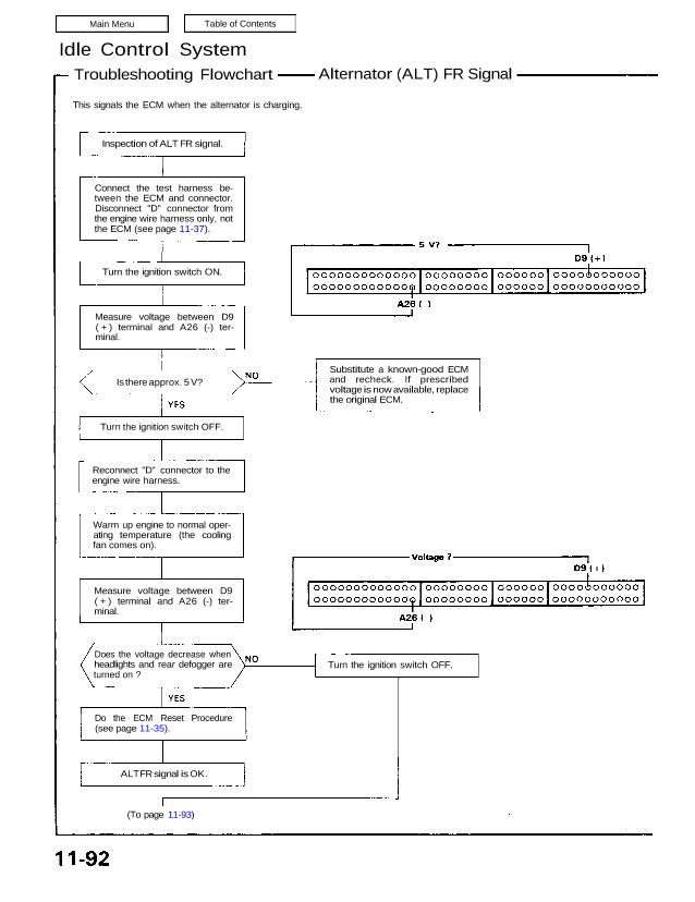
Troubleshooting Flowchart Alternator (ALT) FR Signal
This signals the ECM when the alternator is charging.
Inspection of ALT FR signal.
Connect the test harness be-
tween the ECM and connector.
Disconnect “D” connector from
the engine wire harness only, not
the ECM (see page 11-37).
Turn the ignition switch ON.
Measure voltage between D9
( + ) terminal and A26 (-) ter-
minal.
Is there approx. 5 V?
Turn the ignition switch OFF.
Reconnect “D” connector to the
engine wire harness.
Warm up engine to normal oper-
ating temperature (the cooling
fan comes on).
Measure voltage between D9
( + ) terminal and A26 (-) ter-
minal.
Does the voltage decrease when
headlights and rear defogger are
turned on ?
Do the ECM Reset Procedure
(see page 11-35).
ALT FR signal is OK.
(To page 11-93)
Substitute a known-good ECM
and recheck. If prescribed
voltage is now available, replace
the original ECM.
Turn the ignition switch OFF.
(From page 11-92)
Disconnect “D” connector from
ECM only, not the engine wire
harness.
Disconnect the negative battery
cable from the battery.
Check for continuity between D9
terminal and body ground.
Does continuity exist ?
Remove the harness covers.
Disconnect GRN connector from
the ALT.
Connect WHT/RED wire to body
ground.
Check for continuity between D9
terminal and body ground.
Does continuity exist ?
Repair open in WHT/RED wire
between ECM (D9) and ALT.
See ALT inspection
(see section 23).
Repair shor in WHT/RED wire
between ECM (D9) and ALT.
Does continuity exist ?
Check for continuity between D9
terminal and body ground.
Disconnect GRN connector from
the ALT.
Remove the harness covers.
See ALT inspection
(see section 23).
GRN CONNECTOR