How to Read Flowcharts
A flowchart is designed to be used from start to final repair. It’s like a map showing you the shortest distance. But
beware: if you go off the “map” anywhere but a “stop” symbol, you can easily get lost.
(bold type)
(bold type)
Describes the conditions or situation to start a troubleshooting flowchart.
Asks you to do something; perform a test, set up a condition etc.
Asks you about the result of an action, then sends you in the appropriate troubleshooting direction.
The end of a series of actions and decisions, describes a final repair action and sometimes directs you
to an earlier part of the flowchart to confirm your repair.
NOTE:
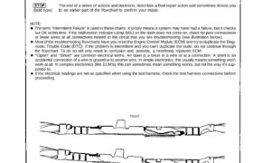
The term “Intermittent Failure” is used in these charts. It simply means a system may have had a failure, but it checks
out OK at this time. If the Malfunction Indicator Lamp (MIL) on the dash does not come on, check for poor connections
or loose wires at all connections related to the circuit that you are troubleshooting (see illustration below).
Most of the troubleshooting flowcharts have you reset the Engine Control Module (ECM) and try to duplicate the Diag-
nostic Trouble Code (DTC). If the problem is intermittent and you can’t duplicate the code, do not continue through
the flowchart. To do so will only result in confusion and, possibly, a needlessly replaced ECM.
“Open” and “Short” are common electrical terms. An open is a break in a wire or at a connection. A short is an
accidental connection of a wire to ground or to another wire. In simple electronics, this usually means something won’t
work at all. In complex electronics (like ECM’s), this can sometimes mean something works, but not the way it’s sup-
posed to.
If the electrical readings are not as specified when using the test harness, check the test harness connections before
proceeding.
TIGHT
LOOSE
A flowchart is designed to be used from start to final repair. It’s like a map showing you the shortest distance. But
beware: if you go off the “map” anywhere but a “stop” symbol, you can easily get lost.
(bold type)
(bold type)
Describes the conditions or situation to start a troubleshooting flowchart.
Asks you to do something; perform a test, set up a condition etc.
Asks you about the result of an action, then sends you in the appropriate troubleshooting direction.
The end of a series of actions and decisions, describes a final repair action and sometimes directs you
to an earlier part of the flowchart to confirm your repair.
NOTE:
The term “Intermittent Failure” is used in these charts. It simply means a system may have had a failure, but it checks
out OK at this time. If the Malfunction Indicator Lamp (MIL) on the dash does not come on, check for poor connections
or loose wires at all connections related to the circuit that you are troubleshooting (see illustration below).
Most of the troubleshooting flowcharts have you reset the Engine Control Module (ECM) and try to duplicate the Diag-
nostic Trouble Code (DTC). If the problem is intermittent and you can’t duplicate the code, do not continue through
the flowchart. To do so will only result in confusion and, possibly, a needlessly replaced ECM.
“Open” and “Short” are common electrical terms. An open is a break in a wire or at a connection. A short is an
accidental connection of a wire to ground or to another wire. In simple electronics, this usually means something won’t
work at all. In complex electronics (like ECM’s), this can sometimes mean something works, but not the way it’s sup-
posed to.
If the electrical readings are not as specified when using the test harness, check the test harness connections before
proceeding.
TIGHT
LOOSE