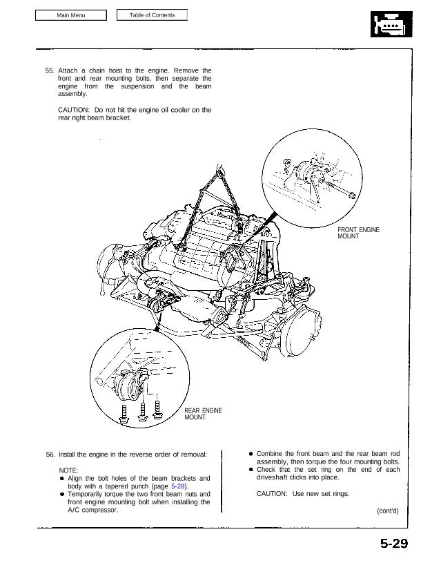
front and rear mounting bolts, then separate the
engine from the suspension and the beam
assembly.
CAUTION: Do not hit the engine oil cooler on the
rear right beam bracket.
FRONT ENGINE
MOUNT
REAR ENGINE
MOUNT
56. Install the engine in the reverse order of removal:
NOTE:
Combine the front beam and the rear beam rod
assembly, then torque the four mounting bolts.
Check that the set ring on the end of each
driveshaft clicks into place.
CAUTION: Use new set rings.
(cont’d)
Align the bolt holes of the beam brackets and
body with a tapered punch (page 5-28).
Temporarily torque the two front beam nuts and
front engine mounting bolt when installing the
A/C compressor.
Engine Removal/Installation
(cont’d)
Torque the engine mounting bolts in sequence
shown below.
CAUTION: Failure to tighten the bolts in the proper
sequence can cause excessive noise and vibration
and reduce bushing life; check that the bushings
are not twisted or offset.
Bleed air from the cooling system (see section 10)
Bleed air from the brake lines (see section 19)
Adjust the throttle cable tension.
Check the clutch pedal free play.
Adjust the clutch guide assemblies when
disassembling clutch (see section 12).
Check that the transmission shifts into gear
smoothly (M/T see section 13, A/T see section 14).
Adjust the alternator belt (see section 23).
Adjust the A/C belt (see section 22).
Clean battery posts and cable terminals with sand-
paper, assemble, then apply grease to prevent
corrosion.
Inspect for fuel leakage:
• After assembling fuel line parts, turn on the igni-
tion switch (do not operate the starter) so that
the fuel pump operates for approximately two
seconds and the fuel line pressurizes. Repeat
this operation two or three times and check
whether any fuel leakage has occurred at any
point in the fuel line.
Check and adjust wheel alignment.
10 x 1.25 mm
60 N.m (6.0 kg-m, 43 Ib-ft)
MOUNTING BOLT
SPECIAL BOLT
12 x 1.25 mm
77 N.m (7.7 kg-m,
56 Ib-ft)
Replace.
10 x 1.25 mm
60 N.m (6.0 kg-m
43 Ib-ft)
73 N.m (7.3 kg-m, 53 Ib-ft)
12 x 1.25 mm
95 N.m (9.5 kg-m,
69 Ib-ft)
RUBBER CAP
(M/T only)
SIDE MOUNT
: CORROSION RESISTANT
BOLT/NUT
12 x 1.25 mm
105 N.m (10.5 kg-m, 76 Ib-ft)
10 x 1.25 mm
60 N.m (6.0 kg-m, 43 Ib-ft)
MOUNTING BOLT
FRONT MOUNT
TRANSMISSION
MOUNT (A/T)
12 x 1.25 mm
95 N.m (9.5 kg-m,
69 Ib-ft)
SEAT STOPPER
TRANSMISSION
MOUNT (A/T)
REAR MOUNT
SPECIAL NUT
12 x 1.25 mm
77 N.m (7.7 kg-m,
56 Ib-ft)
Replace.
M/T:
A/T:
After the engine is in place:
Additional Torque Value Specifications:
NOTE: For manifold replacement, refer to section 9.
ENGINE HANGER
8 x 1.25 mm
30 N.m (3.0 kg-m,
22 Ib-ft)
A/T TRANSMISSION HANGERS
8 x 1.25 mm
30 N.m
(3.0 kg-m,
22 Ib-ft)
M/T TRANSMISSION
HANGERS
12 x 1.25 mm
75 N.m (7.5 kg-m, 54 Ib-ft) 6 x 1.0 mm
10 N.m (1.0 kg-m, 7 Ib-ft)
8 x 1.25 mm
22 N.m (2.2 kg-m,
16 Ib-ft)
HALF SHAFT
SUPPORT BASE
(cont’d)
HALF SHAFT
HEAT COVER
8 x 1.25 mm
22 N.m (2.2 kg-m,
16 Ib-ft)
A/C BRACKET
HALF SHAFT
10 x 1.25 mm
45 N.m (4.5 kg-m,
33 Ib-ft)
ALTERNATOR
BRACKET
STIFFENER
8 x 1.25 mm
22 N.m (2.2 kg-m,
16 Ib-ft)
8x 1.25 mm
22 N.m (2.2 kg-m,
16 Ib-ft)
10 x 1.25 mm
45 N.m (4.5 kg-m,
33 Ib-ft)
ALTERNATOR
BRACKET
8 x 1.25 mm
22 N.m (2.2 kg-m,
16 Ib-ft)
Engine Removal/Installation
(cont’d)
Sub-frame Torque Value Specifications:
RIGHT REAR
BRACKET 10 x 1.25 mm
60 N.m (6.0 kg-m.
43 Ib-ft)
LEFT REAR
BRACKET
10 x 1.25 mm
60 N.m (6.0 kg-m
43 Ib-ft)
10 x 1.25mm
60 N.m (6.0 kg-m, 43 Ib-ft)
CORROSION RESISTANT BOLT/NUT
12 x 1.25 mm
95 N.m (9.5 kg-m, 69 Ib-ft)
10 x 1.25 mm
60 N.m (6.0 kg-m, 43 Ib-ft)
ROD A10 x 1.25 mm
60 N.m (6.0 kg-m,
43 Ib-ft)
FRONT BEAM
REAR BEAM
12 x 1.25 mm
95 N.m
(9.5 kg-m,
69 Ib-ft)
ROD B
10 x 1.25 mm
60 N.m (6.0 kg-m, 43 Ib-ft)
CENTER ROD