Interlock System
Shift Lock Solenoid Test/Replacement
Test:
1. Remove the console, then disconnect the 3-P con-
nector of the shift lock solenoid from the floor wire
harness.
NOTE: This solenoid has a diode in it. To get an
accurate reading, either test it with a volt-ohmmeter
that compensates for diodes, or make sure you con-
nect your test leads to match the polarity shown.
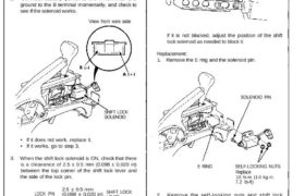
2. Connect battery power to the A terminal and
ground to the B terminal momentarily, and check to
see if the solenoid works.
View from wire side
SHIFT LOCK
SOLENOID
• If it does not work, replace it.
• If it works, go to step 3.
3. When the shift lock solenoid is ON, check that there
is a clearance of 2.5 ± 0.5 mm (0.098 ± 0.020 in)
between the top corner of the shift lock lever and
the side of the lock pin.
• If clearance is correct, go to next step.
• If clearance is incorrect, loosen the self-locking
nuts and adjust the solenoid as needed.
4. When the shift lock solenoid is OFF, make sure that
the lock pin is blocked by the top of the shift lock lever.
LOCK PIN
SHIFT LOCK
LEVER
If it is not blocked, adjust the position of the shift
lock solenoid as needed to block it.
Replacement:
1. Remove the E ring and the solenoid pin.
SOLENOID PIN
E RING SELF-LOCKING NUTS
Replace
10 N-m (1.0 kg-m,
7.2 Ib-ft)
2. Remove the self-looking nuts and shift lock
solenoid.
3. Install the new shift lock solenoid in the reverse
order of removal.
4. Check the position of the shift lock solenoid as
described in steps 3 and 4.
LOCK PIN
2.5 ± 0.5 mm
(0.098 ± 0.020 in) SHIFT LOCKLEVER
Shift Lock Solenoid Test/Replacement
Test:
1. Remove the console, then disconnect the 3-P con-
nector of the shift lock solenoid from the floor wire
harness.
NOTE: This solenoid has a diode in it. To get an
accurate reading, either test it with a volt-ohmmeter
that compensates for diodes, or make sure you con-
nect your test leads to match the polarity shown.
2. Connect battery power to the A terminal and
ground to the B terminal momentarily, and check to
see if the solenoid works.
View from wire side
SHIFT LOCK
SOLENOID
• If it does not work, replace it.
• If it works, go to step 3.
3. When the shift lock solenoid is ON, check that there
is a clearance of 2.5 ± 0.5 mm (0.098 ± 0.020 in)
between the top corner of the shift lock lever and
the side of the lock pin.
• If clearance is correct, go to next step.
• If clearance is incorrect, loosen the self-locking
nuts and adjust the solenoid as needed.
4. When the shift lock solenoid is OFF, make sure that
the lock pin is blocked by the top of the shift lock lever.
LOCK PIN
SHIFT LOCK
LEVER
If it is not blocked, adjust the position of the shift
lock solenoid as needed to block it.
Replacement:
1. Remove the E ring and the solenoid pin.
SOLENOID PIN
E RING SELF-LOCKING NUTS
Replace
10 N-m (1.0 kg-m,
7.2 Ib-ft)
2. Remove the self-looking nuts and shift lock
solenoid.
3. Install the new shift lock solenoid in the reverse
order of removal.
4. Check the position of the shift lock solenoid as
described in steps 3 and 4.
LOCK PIN
2.5 ± 0.5 mm
(0.098 ± 0.020 in) SHIFT LOCKLEVER