Replacement
SRS components are located in this area. Review the SRS
component locations, precautions, and procedures in the
SRS section (24) before performing repairs or service.
1. Remove the blower unit (see page 22-67 (’93-’96),
63(’91-’92)).
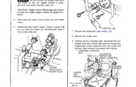
2. When the engine is cool, drain the engine coolant
from the radiator (see section 10).
Do not remove the radiator cap when
the engine is hot; the engine coolant is under
pressure and could severely scald you.
CAUTION: Engine coolant will damage paint. Quick-
ly rinse any spilled engine coolant off painted sur-
faces.
3. Disconnect the heater valve cable from the heater
valve.
4. Disconnect the heater hoses. Engine cootant will
run out when the hoses are disconnected, drain it
into a clean drip pan.
HEATER
VALVE CASLE
HEATER VALVE
5. Recover the refrigerant from the A/C system with a
R-134a refrigerant Recovery/Recycling/Charging
System. (see page 22-73).
6. Disconnect the receiver line and the suction line from
the evaporator. Cap the open fittings immediately
to keep moisture out of the system.
RECEIVER LINE
New parts (R-134a)
SECTION LINE
7. Remove the dashboard (see section 20).
8. Remove the heater duct.
9. Remove the four mounting bolts, disconnect the con-
nectors from the control units and the evaporator
temperature sensor connector from the control unit
bracket, then remove the control unit bracket.
*: CORROSION RESISTANT
BOLT EVAPORATOR
TEMPERATURE
SENSOR CONNECTOR
CONTROL
UNIT
BRACKET
SRS MAIN
HARNESS
* 6 x 1,0 mm
10 N·m
(1.0 kg-m,
7 Ib-ft)
* 6 x 1.0 mm
10 N·m (1.0 kg-m, 7 Ib-ft)
10. Remove the woofer enclosure (see section 23).
11. Disconnect the connectors from all the control
motors and sensors attached to the heater-
evaporator unit.
12. Remove the two mounting bolts and two nuts, then
remove the heater-evaporator unit through the
passenger door.
: CORROSION RESISTANT
BOLT
HEATER-EVAPORATOR UNIT
NUTS
30 N·m (3.0 kg-m,
22 Ib-ft)
SRS UNIT
6 x 1.0 mm
10 N·m (1.0 kg-m, 7 Ib-ft)
13. Install the heater-evaporator unit in the reverse
order of removal, and:
If you’re installing a new evaporator, add
refrigerant oil (ND-OIL 8) see page 22-69 .
Replace 0-rings with new ones at each fitting,
and apply refrigerant oil to them.
NOTE: Be sure to use the right 0-rings for
R-134a to avoid leakage.
14. Fill the radiator and reservoir tank with the proper
engine coolant mixture. Bleed the air from the cool-
ing system (see section 10).
CAUTION: Follow the sequence described in the air
bleed procedure. If you don’t, you may leave air in
the system which could damage the engine.
15. If necessary, adjust the heater valve cable:
Set the air mix control motor at COOL position
(see page 22-57) .
Connect the end of the heater valve cable to the
heater valve arm.
Gently slide the cable outer housing back from
the end enough to take up any slack in the cable,
but not enough to make the other end move the
arm on the air mix control motor. Then snap the
clamp down over the cable housing.
CLAMP
HEATER VALVE
ARM
HEATER VALVE
CABLE
16. Turn the blower on, and make sure that there is no
air leakage.
17. Charge the system (see page 22-91), and test per-
formance (see page 22-70).