Rear Hatch/Engine Cover
Replacement/Adjustment
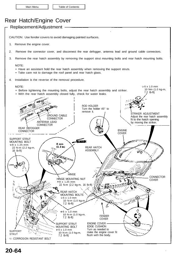
CAUTION: Use fender covers to avoid damaging painted surfaces.
1. Remove the engine cover.
2. Remove the connector cover, and disconnect the rear defogger, antenna lead and ground cable connectors.
3. Remove the rear hatch assembly by removing the support strut mounting bolts and rear hatch mounting bolts.
NOTE:
• Have an assistant hold the rear hatch assembly when removing the support struts.
• Take care not to damage the roof panel and rear hatch glass.
4. Installation is the reverse of the removal procedure.
NOTE:
• Before tightening the mounting bolts, adjust the rear hatch assembly and striker.
• With the rear hatch assembly closed fully, check for water leaks.
ROD HOLDER
Turn the holder 45° to
remove it.
6 x 1.0 mm
10 Nm (1.0 kg-m,
7.2 Ib-ft)
GROUND CABLE
CONNECTOR
ANTENNA LEAD
CONNECTOR
STRIKER ADJUSTMENT
Adjust the rear hatch assembly
fit to the hatch opening
by moving the striker.
REAR DEFOGGER
CONNECTOR
SUPPORT STRUT
MOUNTING BOLT
8 x 1.25 mm
22 N-m (2.2 kg-m,
16 Ib-ft)
6 x 1.0 mm
10 N-m (1.0 kg-m,
7.2 Ib-ft)
SUPPORT
STRUT
CORROSION RESISTANT BOLT
SUPPORT STRUT
MOUNTING BOLT
6 x 1.0 mm
10 N-m (1.0 kg-m,
7.2 Ib-ft)
CONNECTOR
COVER
ENGINE COVER
EDGE CUSHION
Turn as needed to
make the engine cover fit
flush with the body.
HINGE MOUNTING NUT
8 x 1.25 mm
22 N-m (2.2 kg-m, 16 Ib-ft)
HINGE
REAR HATCH
ASSEMBLY
ENGINE
COVER
FENDER
COVER
REAR HATCH
MOUNTING BOLTS
6 x 1.0 mm
10 N-m (1.0 kg-m,
7.2 Ib-ft)
Replacement/Adjustment
CAUTION: Use fender covers to avoid damaging painted surfaces.
1. Remove the engine cover.
2. Remove the connector cover, and disconnect the rear defogger, antenna lead and ground cable connectors.
3. Remove the rear hatch assembly by removing the support strut mounting bolts and rear hatch mounting bolts.
NOTE:
• Have an assistant hold the rear hatch assembly when removing the support struts.
• Take care not to damage the roof panel and rear hatch glass.
4. Installation is the reverse of the removal procedure.
NOTE:
• Before tightening the mounting bolts, adjust the rear hatch assembly and striker.
• With the rear hatch assembly closed fully, check for water leaks.
ROD HOLDER
Turn the holder 45° to
remove it.
6 x 1.0 mm
10 Nm (1.0 kg-m,
7.2 Ib-ft)
GROUND CABLE
CONNECTOR
ANTENNA LEAD
CONNECTOR
STRIKER ADJUSTMENT
Adjust the rear hatch assembly
fit to the hatch opening
by moving the striker.
REAR DEFOGGER
CONNECTOR
SUPPORT STRUT
MOUNTING BOLT
8 x 1.25 mm
22 N-m (2.2 kg-m,
16 Ib-ft)
6 x 1.0 mm
10 N-m (1.0 kg-m,
7.2 Ib-ft)
SUPPORT
STRUT
CORROSION RESISTANT BOLT
SUPPORT STRUT
MOUNTING BOLT
6 x 1.0 mm
10 N-m (1.0 kg-m,
7.2 Ib-ft)
CONNECTOR
COVER
ENGINE COVER
EDGE CUSHION
Turn as needed to
make the engine cover fit
flush with the body.
HINGE MOUNTING NUT
8 x 1.25 mm
22 N-m (2.2 kg-m, 16 Ib-ft)
HINGE
REAR HATCH
ASSEMBLY
ENGINE
COVER
FENDER
COVER
REAR HATCH
MOUNTING BOLTS
6 x 1.0 mm
10 N-m (1.0 kg-m,
7.2 Ib-ft)