Electronic Components
TCS Switch Inspection
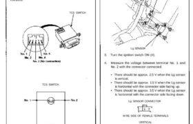
Between terminal No. 4 and No. 5
(Illumination light circuit)
There should be continuity.
Between terminal No. 1 and No. 2
(Switch circuit)
There should be continuity when the switch is pushed,
and there should be no continuity when the switch is
released.
TCS SWITCH
TCS SWITCH
Lateral Acceleration (Lg) Sensor
Inspection
CAUTION: Be careful not to drop or bump the Lg sensor,
and don’t remove or install it with an impact wrench;
the Lg sensor may be damaged.
1. Remove the rear center trim panel (see section 20).
2. Remove the Lg sensor from the bracket.
BRACKET
Lg SENSOR
3. Turn the ignition switch ON (II).
4. Measure the voltage between terminal No. 1 and
No. 2 with the connector connected.
• There should be approx. 2.5 V when the Lg sensor
is vertical.
• There should be approx. 1.5 V when the Lg sensor
is horizontal with the connector side facing up.
• There should be approx. 3.5 V when the Lg sensor
is horizontal with the connector side facing down.
Lg SENSOR CONNECTOR
WIRE SIDE OF FEMALE TERMINALS
VERTICAL
Lg SENSOR
CONNECTOR
CONNECTOR SIDE FACING UP
CONNECTOR
CONNECTOR SIDE FACING DOWN
CONNECTOR
TCS Switch Inspection
Between terminal No. 4 and No. 5
(Illumination light circuit)
There should be continuity.
Between terminal No. 1 and No. 2
(Switch circuit)
There should be continuity when the switch is pushed,
and there should be no continuity when the switch is
released.
TCS SWITCH
TCS SWITCH
Lateral Acceleration (Lg) Sensor
Inspection
CAUTION: Be careful not to drop or bump the Lg sensor,
and don’t remove or install it with an impact wrench;
the Lg sensor may be damaged.
1. Remove the rear center trim panel (see section 20).
2. Remove the Lg sensor from the bracket.
BRACKET
Lg SENSOR
3. Turn the ignition switch ON (II).
4. Measure the voltage between terminal No. 1 and
No. 2 with the connector connected.
• There should be approx. 2.5 V when the Lg sensor
is vertical.
• There should be approx. 1.5 V when the Lg sensor
is horizontal with the connector side facing up.
• There should be approx. 3.5 V when the Lg sensor
is horizontal with the connector side facing down.
Lg SENSOR CONNECTOR
WIRE SIDE OF FEMALE TERMINALS
VERTICAL
Lg SENSOR
CONNECTOR
CONNECTOR SIDE FACING UP
CONNECTOR
CONNECTOR SIDE FACING DOWN
CONNECTOR