Knuckle/Control Arms/Compliance Pivot
Ball Joint Boot Replacement
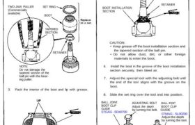
NOTE:
Do not damage the
tapered section of the
ball pin with the bear-
ing puller.
3. Pack the interior of the boot and lip with grease.
BOOT INSTALLATION SECTION
CAUTION: Do not contaminate the boot installa-
tion section with grease.
4. Wipe the grease off the sliding surface of the ball
pin, and pack with fresh grease.
5. Insert the new retainer lightly into the ball joint pin.
NOTE: When installing the ball joint, press the re-
tainer into the ball joint pin.
BALL PIN TAPERED SECTION
BOOT INSTALLATION
SECTION
CAUTION:
• Keep grease off the boot installation section and
the tapered section of the ball pin.
• Do not allow dust, dirt, or other foreign
materials to enter the boot.
6. Install the boot in the groove of the boot installation
section securely, then bleed air.
7. Adjust the special tool with the adjusting bolt until
the end of the tool aligns with the groove on the
boot.
8. Slide the set ring over the tool and into position.
BALL JOINT.
BOOT CLIP
GUIDE
07GAG – SD40700
SET RING
BOOT
ADJUSTING BOLT BALL JO|NT
Adjust the depth BOOT CLIP
by turning the bolt. GUIDE
07MAG – SL00200
Adjust the depth
by turning the tool.
upper knuckle and
upper/lower control arm.
knuckle lower ball joint
only.
CAUTION: After installing the boot, check the ball
pin tapered section and threads for grease con-
tamination and wipe them if necessary.
NOTE: The upper control arm ball joint, lower control
arm ball joint and knuckle upper ball joint are attached
with the boot retainer to improve the sealing efficiency
of the boot.
1. Remove the set ring and boot.
2. Remove the retainer.
NOTE: The knuckle lower ball joint does not have a
retainer.
TWO-JAW PULLER
(Commercially
available)
SET RING
BOOT
TAPERED
SECTION
RETAINER
RETAINER
SET RING
BOOT
Ball Joint Boot Replacement
NOTE:
Do not damage the
tapered section of the
ball pin with the bear-
ing puller.
3. Pack the interior of the boot and lip with grease.
BOOT INSTALLATION SECTION
CAUTION: Do not contaminate the boot installa-
tion section with grease.
4. Wipe the grease off the sliding surface of the ball
pin, and pack with fresh grease.
5. Insert the new retainer lightly into the ball joint pin.
NOTE: When installing the ball joint, press the re-
tainer into the ball joint pin.
BALL PIN TAPERED SECTION
BOOT INSTALLATION
SECTION
CAUTION:
• Keep grease off the boot installation section and
the tapered section of the ball pin.
• Do not allow dust, dirt, or other foreign
materials to enter the boot.
6. Install the boot in the groove of the boot installation
section securely, then bleed air.
7. Adjust the special tool with the adjusting bolt until
the end of the tool aligns with the groove on the
boot.
8. Slide the set ring over the tool and into position.
BALL JOINT.
BOOT CLIP
GUIDE
07GAG – SD40700
SET RING
BOOT
ADJUSTING BOLT BALL JO|NT
Adjust the depth BOOT CLIP
by turning the bolt. GUIDE
07MAG – SL00200
Adjust the depth
by turning the tool.
upper knuckle and
upper/lower control arm.
knuckle lower ball joint
only.
CAUTION: After installing the boot, check the ball
pin tapered section and threads for grease con-
tamination and wipe them if necessary.
NOTE: The upper control arm ball joint, lower control
arm ball joint and knuckle upper ball joint are attached
with the boot retainer to improve the sealing efficiency
of the boot.
1. Remove the set ring and boot.
2. Remove the retainer.
NOTE: The knuckle lower ball joint does not have a
retainer.
TWO-JAW PULLER
(Commercially
available)
SET RING
BOOT
TAPERED
SECTION
RETAINER
RETAINER
SET RING
BOOT