Reassembly
Outboard joint side
NOTE: Wrap the splines with vinyl tape to prevent
damage to the boot.
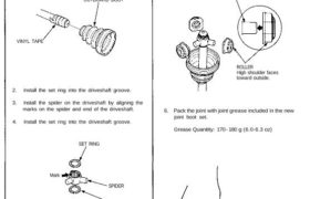
1. Install the outboard boot to the driveshaft, then
remove the vinyl tape.
OUTBOARD BOOT
VINYL TAPE
2. Install the set ring into the driveshaft groove.
3. Install the spider on the driveshaft by aligning the
marks on the spider and end of the driveshaft.
4. Install the set ring into the driveshaft groove.
SET RING
Mark
Mark
SPIDER
SET RING
5. Fit the rollers to the spider with their high shoulders
facing outward.
CAUTION:
• Reinstall the rollers in their original positions on
the spider.
• Hold the driveshaft assembly pointed up to pre-
vent the rollers from falling off.
SPIDER
ROLLER
High shoulder faces
toward outside.
6. Pack the joint with joint grease included in the new
joint boot set.
Grease Quantity: 170 – 180 g (6.0-6.3 oz)
7. Install the spring and cap, then fit the outboard
joint onto the driveshaft.
OUTBOARD JOINT
Align the roller holders with the
inboard joint as shown
below.
Spline
direction
HOLDER
8. Fit the circlip into the outboard joint inner groove.
CIRCLIP
Inboard joint side
NOTE: Wrap the splines with vinyl tape to prevent
damage to the boot.
9. Install the inboard boot to the driveshaft, then
remove the vinyl tape.
INBOARD BOOT
VINYL TAPE
10. Install the set ring into the driveshaft groove.
11. Install the spider on the driveshaft by aligning the
marks on the spider and end of the driveshaft.
12. Install the set ring into the driveshaft groove.
SET RING
Mark
SET RING
Mark
SPIDER
SPRING
CAP
Driveshafts
Reassembly
13. Fit the rollers to the spider with their high shoulders
facing outward.
CAUTION:
• Reinstall the rollers in their original positions on
the spider.
• Hold the driveshaft assembly with the rollers up
to prevent them from falling off.
SPIDER
ROLLER
High shoulder faces
toward outside.
14. Pack the joint with joint grease included in the new
joint boot set.
Grease Quantity: 120-130 g (4.2-4.6 oz)
1 5. Fit the inboard joint onto the driveshaft.
INBOARD JOINT
Align the roller holders with the
inboard joint as shown
below.
HOLDER
16. Adjust the length of the driveshafts to the figure
below, then adjust the boots to halfway between
full compression and extension.
NOTE: The ends of the boots seat in the grooves
of the driveshaft and joint.
Left Driveshaft
M/T: 501.0-506.0 mm (19.72-19.92 in)
A/T: 507.0-512.0 mm (19.96-20.16 in)
Right Driveshaft
M/T and A/T: 542.0-547.0 mm (21.34-21.54 in)
Spline
direction
17. Install new boot bands on the boots, then bend both
sets of locking tabs.
18. Lightly tap on the doubled-over portions to reduce
their height.
NOTE: Install the outboard joint in the knuckle
before installing the driveshaft into the differential
or intermediate shaft. Loosely install the spindle
nut this time.
19. Install the new set rings in the driveshaft groove
and intermediate shaft groove.
20. Apply a light film of grease around the set ring groove
on the inboard joint, then install a new set ring and
center it on the joint. The grease will keep the set
ring centered, making the installation of the joint
easier.
21. Install the inboard end of the driveshaft into dif-
ferential or intermediate shaft.
CAUTION:
• Always use a new set ring whenever the drive-
shaft is being installed.
• Make sure the left driveshaft locks in the dif-
ferential side gear groove, and the CV joint
subaxle bottoms in the differential.
• Insert the right driveshaft CV joint subaxle into
the intermediate shaft until the intermediate
shaft set ring locks in the groove in the right
driveshaft.
Apply light film of
grease before installing.
INBOARD JOINT
SET RING
Replace.
SET RING GROOVE
Left Driveshaft
inboard end
Right Driveshaft
inboard end
(Intermediate shaft side)
LOCKING TABS