Installation
NOTE:
• Install the pressure plate, clutch discs, and mid plate
as a set.
• Do not mix-up the 1st and 2nd clutch discs. The 2nd
clutch disc has a flat plate between the two friction
surfaces. The 1st clutch disc has a spring plate be-
tween the two friction surfaces.
• Use only Super High Temp Urea Grease (P/N
08798-9002).
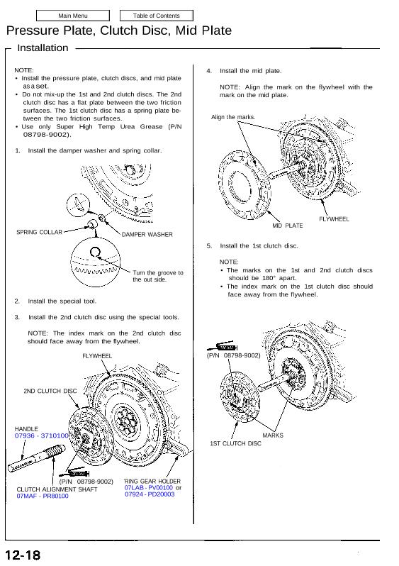
1. Install the damper washer and spring collar.
SPRING COLLAR DAMPER WASHER
Turn the groove to
the out side.
2. Install the special tool.
3. Install the 2nd clutch disc using the special tools.
NOTE: The index mark on the 2nd clutch disc
should face away from the flywheel.
FLYWHEEL
2ND CLUTCH DISC
HANDLE
07936 – 3710100
(P/N 08798-9002)
CLUTCH ALIGNMENT SHAFT
07MAF – PR80100
RING GEAR HOLDER
07LAB – PV00100 or
07924 – PD20003
4. Install the mid plate.
NOTE: Align the mark on the flywheel with the
mark on the mid plate.
Align the marks.
FLYWHEEL
MID PLATE
5. Install the 1st clutch disc.
NOTE:
• The marks on the 1st and 2nd clutch discs
should be 180° apart.
• The index mark on the 1st clutch disc should
face away from the flywheel.
MARKS
1ST CLUTCH DISC
(P/N 08798-9002)
6. Install the release bearing on the pressure plate.
7. Install the pressure plate.
NOTE:
Align the mark on the mid plate with the mark on
the pressure plate.
After installing, make sure the release bearing is
secure.
Align the marks.
PRESSURE PLATE
RELEASE BEARING
PRESSURE PLATE
(P/N 08798-9002)
RELEASE
BEARING
Place the diaphragm spring fingers
in the groove of the release bearing.
9. Remove the special tools.
10. Initialize the mid plate guides (see page 12-14
(’93-’96), 12-16 (’91-’92 Models).
MOUNTING BOLT
8 x 1.25 mm
22 N·m (2.2 kg-m, 16 Ib-ft)
8. Torque the mounting bolts in a crisscross pattern
as shown. Tighten them several steps to prevent
warping the diaphragm spring.
NOTE: Place the diaphragm spring fingers in the
groove of the release bearing.