Category: Automatic Transmission
nsxd14157a.pdf
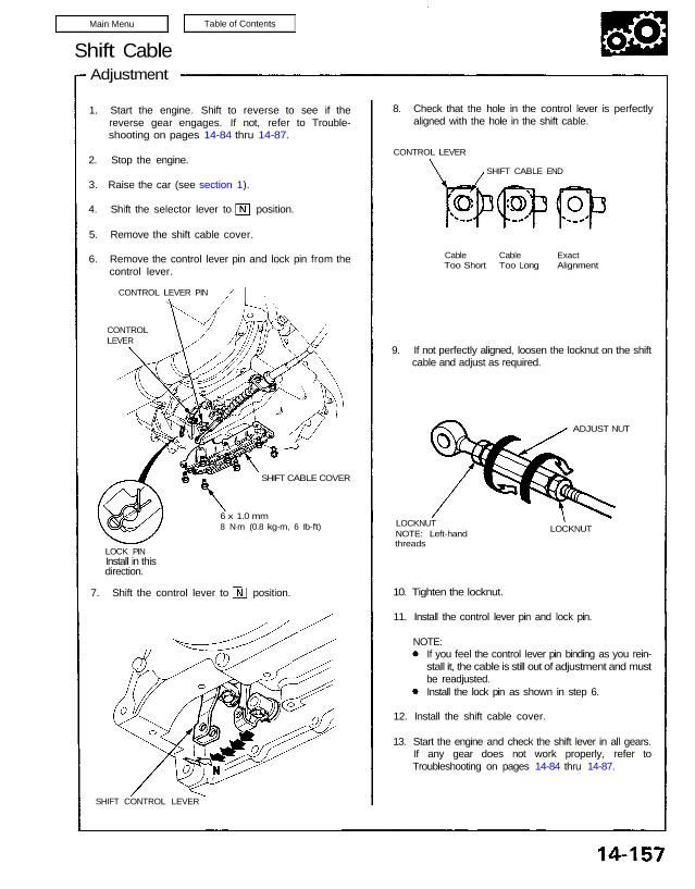
Shift Cable Adjustment 1. Start the engine. Shift to reverse to see if the reverse gear engages. If not, refer to Trouble- shooting on pages 14-84 thru 14-87. 2. Stop the engine. 3. Raise the car (see section 1). 4. Shift the selector lever to position. 5. Remove the shift cable cover. 6. Remove the […]
nsxd14091a.pdf
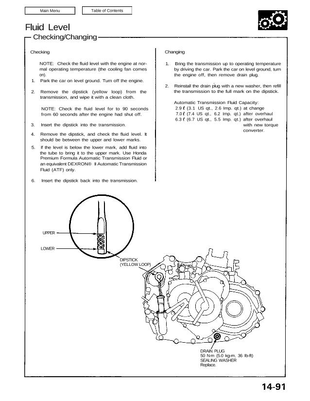
Fluid Level Checking/Changing Checking NOTE: Check the fluid level with the engine at nor- mal operating temperature (the cooling fan comes on). 1. Park the car on level ground. Turn off the engine. 2. Remove the dipstick (yellow loop) from the transmission, and wipe it with a clean cloth. NOTE: Check the fluid level for […]
nsxd14028a.pdf
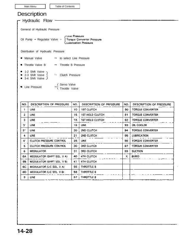
Description Hydraulic Flow General of Hydraulic Pressure Oil Pump Regulator Valve Distribution of Hydrualic Pressure Manual Valve Throttle Valve B 1-2 Shift Valve 2-3 Shift Valve 3-4 Shift Valve to select Line Pressure Throttle B Pressure Clutch Pressure Servo Valve Throttle ValveLine Pressure As the engine turns, the oil pump also starts to operate. Automatic […]
nsxd14050a.pdf
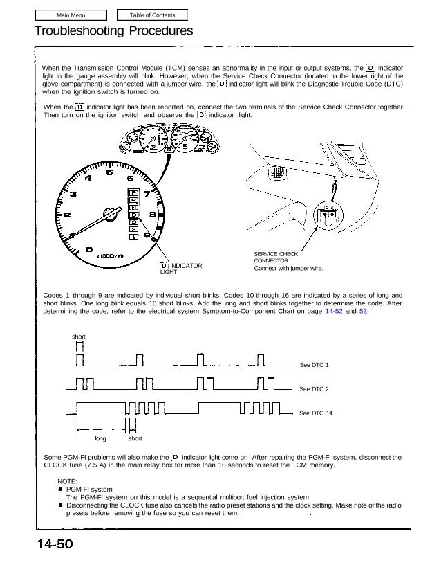
Troubleshooting Procedures When the Transmission Control Module (TCM) senses an abnormality in the input or output systems, the indicator light in the gauge assembly will blink. However, when the Service Check Connector (located to the lower right of the glove compartment) is connected with a jumper wire, the indicator light will blink the Diagnostic Trouble […]
nsxd14143a.pdf
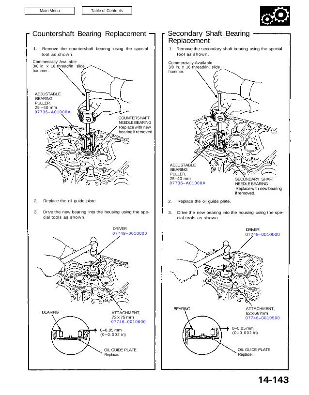
OIL GUIDE PLATE Replace. 0–0.05 mm (0–0 .002 in) ATTACHMENT, 62 x 68 mm 07746–0010500 BEARING OIL GUIDE PLATE Replace. 0–0.05 mm (0–0.002 in) ATTACHMENT, 72 x 75 mm 07746–0010600 BEARING DRIVER 07749–0010000 2. Replace the oil guide plate. 3. Drive the new bearing into the housing using the spe- cial tools as shown. COUNTERSHAFT […]
nsxd14132a.pdf
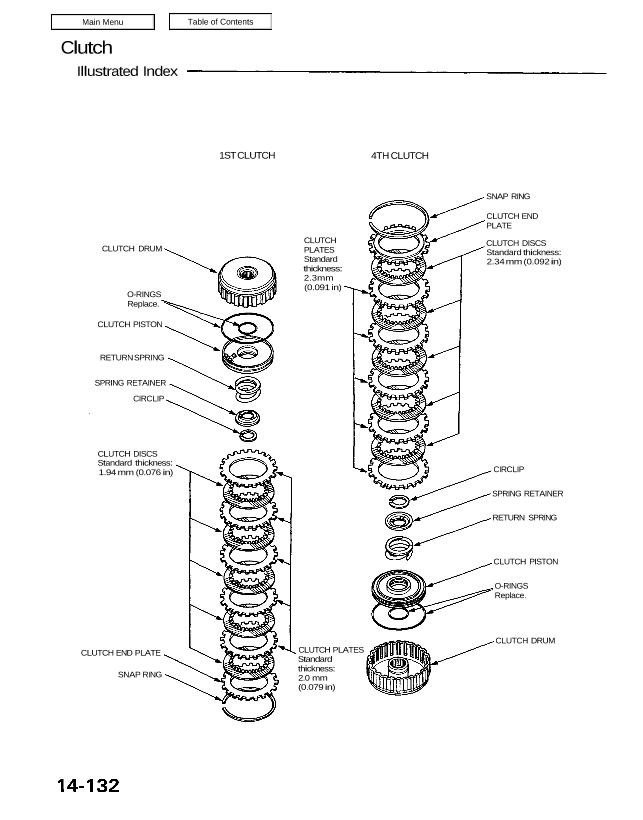
Clutch Illustrated Index 1ST CLUTCH 4TH CLUTCH SNAP RING CLUTCH END PLATE CLUTCH DISCS Standard thickness: 2.34 mm (0.092 in) CLUTCH PLATES Standard thickness: 2.3mm (0.091 in) CLUTCH DRUM O-RINGS Replace. CLUTCH PISTON RETURN SPRING SPRING RETAINER CIRCLIP CLUTCH DISCS Standard thickness: 1.94 mm (0.076 in) CIRCLIP SPRING RETAINER RETURN SPRING CLUTCH PISTON O-RINGS Replace. […]
nsxd14079a.pdf
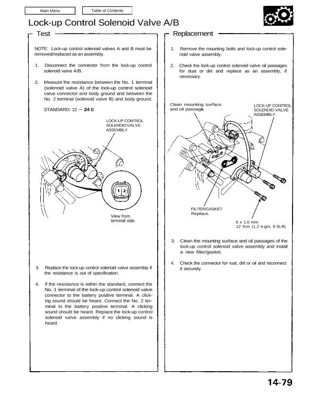
Lock-up Control Solenoid Valve A/B Test NOTE: Lock-up control solenoid valves A and B must be removed/replaced as an assembly. 1. Disconnect the connector from the lock-up control solenoid valve A/B. 2. Measure the resistance between the No. 1 terminal (solenoid valve A) of the lock-up control solenoid valve connector and body ground and between […]
nsxd14124a.pdf
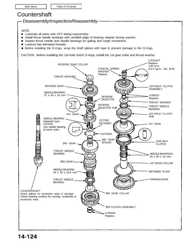
O-RINGS Replace. 3RD CLUTCH ASSEMBLY 3RD GEAR COLLAR PARKING GEAR RETAINER PLATE 1ST GEAR COLLAR NEEDLE BEARINGS 34 x 40 x 20 mm ONE-WAY CLUTCH 1ST GEAR 1ST-HOLD CLUTCH HUB THRUST NEEDLE BEARING THRUST WASHER O-RINGS Replace. 1ST-HOLD CLUTCH ASSEMBLY LOCKNUT Replace. 140 N·m (14.0 kg-m, 101 Ib-ft)CONICAL SPRING REVERSE GEAR COLLAR THRUST WASHER REVERSE […]
nsxd14104a.pdf
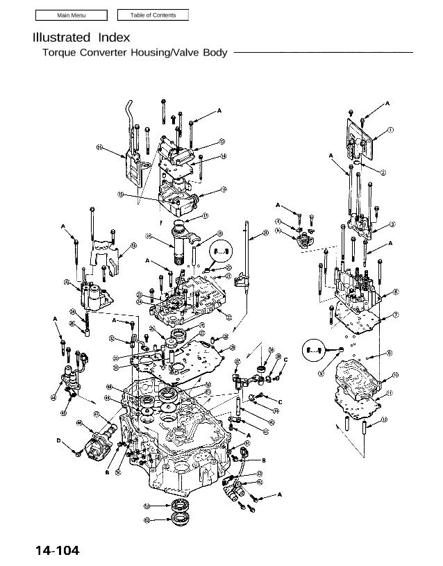
Illustrated Index Torque Converter Housing/Valve Body Table of Contents Main Menu Illustrated Index Torque Converter Housing/Valve Body 14-104 ATF STRAIER Clean or replace. O-RING Replace. ACCUMULATOR COVER LOCK WASHER Replace. SERVO DETENT BASE SERVO VALVE BODY SERVO SEPARATOR PLATE CHECK BALLS (7/32) 7 SECONDARY VALVE BODY FILTER Replace. SECONDARY VALVE BODY SECONDARY SEPARATOR PLATE DOWEL […]
nsxd14096a.pdf

Transmission Removal Make sure lifts are placed properly, and hoist brackets are attached to correct position (see sec- tion 1). CAUTION: Use fender covers to avoid damaging painted surfaces. 1. Check and record the rear camber. (see section 18.) 2. Disconnect the battery negative (-) first, and positive (+) cable from the battery. 3. Drain […]