Hydraulic Flow
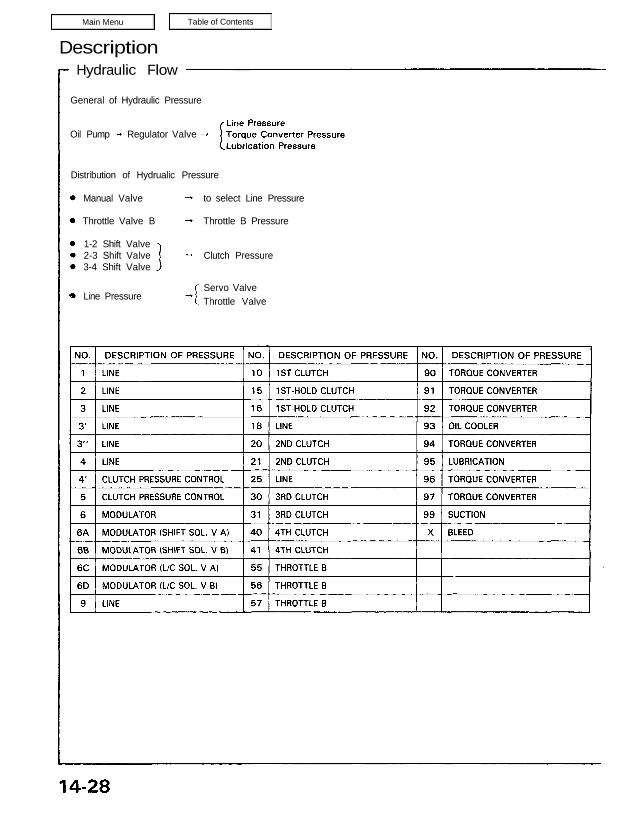
General of Hydraulic Pressure
Oil Pump Regulator Valve
Distribution of Hydrualic Pressure
Manual Valve
Throttle Valve B
1-2 Shift Valve
2-3 Shift Valve
3-4 Shift Valve
to select Line Pressure
Throttle B Pressure
Clutch Pressure
Servo Valve
Throttle ValveLine Pressure
As the engine turns, the oil pump also starts to operate. Automatic transmission fluid (ATF) is drawn from (99) and
discharged into (1). Then, ATF pressure is controled by the regulator valve and becomes line pressure (1). The torque
converter inlet pressure (92) enters (94) of torque converter through the orifice and discharges into (90).
The torque converter check valve prevents the torque converter pressure from rising.
Under this condition, the hydraulic pressure is not applied to the clutches.
(cont’d)
position
Description
Hydraulic Flow (cont’d)
The line pressure (1) becomes the line pressure (4), (18), (25) as it passes through the manual valve. Also, the line pressure
(1) goes to the modulator valve through the filter and becomes the modulator pressure (6). The modulator pressure (6)
is supplied to the 1-2 shift valve and 2-3 shift valve.
The 1 -2 shift and 2-3 shift valves are moved to the left side because the shift control solenoid valve A is turned ON and B
is OFF by the TCM.
The line pressure (18) is supplied to the 3-4 shift valve, and it is moved to the left side. The line pressure (4) is the 1st
clutch pressure (10), then the 1st clutch is engaged.
The line pressure (4) becomes the 1st-hold clutch pressure (16) via the 1-2 shift valve, 2-3 shift valve, 3-4 shift valve
and manual valve, then the 1st-hold clutch is engaged.
NOTE: When used, “left” or “right” indicates direction on the flowchart.
Position
The line pressure (1) becomes the line pressure (4), (25) as it passes through the manual valve.
The line pressure (1) goes to the modulator valve and becomes the modulator pressure (6). The modulator pressure (6)
is supplied to the 1-2 shift valve and 3-4 shift valve. The 1-2 shift and 3-4 shift valves are moved to the left side and
the 2-3 shift valve is moved to the right side because the shift control solenoid valve A and B are turned OFF by the
TCM.
The line pressure (4) goes through the 2nd clutch pressure (20) to the 2nd clutch, then the 2nd clutch is engaged.
The line pressure (4) passing through the orifice becomes the 1st clutch pressure (10) and flows to the 1st clutch.
However no power is transmitted by means of the one-way clutch.
NOTE: When used, “left” or “right” indicates direction on the flowchart.
(cont’d)
Position
Description
Hydraulic Flow (cont’d)
The line pressure (1) becomes the modulator pressure (6) as it passes the modulator valve.
Also, the modulator pressure (6) is supplied to the 1 -2 shift valve and 2-3 shift valve, and they are moved to the left side
because the shift control solenoid A is turned ON and B is OFF by the TCM.
The line pressure (4) becomes the clutch pressure control (5) and the 3rd clutch pressure (31).
Then it goes to the 3rd clutch. The 3rd clutch is engaged.
The line pressure (4) passing through the orifice becomes the 1st clutch pressure (10) and flows to the 1st clutch.
However no power is transmitted by means of the one-way clutch as in 2nd speed.
NOTE: When used, “left” or “right” indicates direction on the flowchart.
Position
1st speed
The flow of fluid through the torque converter circuit is the same as in position.
The line pressure (1) becomes the line pressure (4) and it becomes the 1st clutch pressure (10).
The 1st clutch pressure is applied to the 1st clutch and 1st accumulator, consequently the vehicle will move as the
engine power is transmitted.
The line pressure (1) becomes the modulator pressure (6) by the modulator valve and travels to each shift valve.
The 1-2 shift valve is moved to the right side because the shift control solenoid valve A is turned OFF and B is ON by
the TCM.
The line pressure (1) also flows to the throttle valve.
NOTE: When used, “left” or “right” indicates direction on the flowchart.
(cont’d)
Position
Description
Hydraulic Flow (cont’d)
2nd.speed
The flow of fluid up to the 1-2 and 2-3 shift valves is the same as in the 1st speed range. As the speed of the car
reaches the prescribed value, the solenoid valve A is turned ON by means of the TCM. As a result, the 1 -2 shift valve
is moved to the left side and uncovers the port leading to the 2nd clutch; the 2nd clutch is engaged.
Fluid flows by way of:
Line Pressure (4)
2-3 Shift Valve
CPC Valve Clutch Pressure Control (4′) 1 -2 Shift Valve Clutch Pressure Control (5)
2nd Clutch Pressure (21) Orifice 2nd Clutch Pressure (20) 2nd Clutch
The hydraulic pressure also flows to the 1 st clutch. However no power is transmitted by means of the one-way
clutch.
NOTE: When used, “left” or “right” indicates direction on the flowchart.
3. 3rd Speed
The flow of fluid up to the 1-2, 2-3 and 3-4 shift valves is the same as in the 2nd speed. As the speed of the car
reaches the prescribed value, the shift control solenoid valve B is turned OFF (Shift control solenoid valve A remains
ON). The 2-3 shift valve is then moved to the left side, uncovering the oil port leading to the 3rd clutch. Since the
3-4 shift valve is moved to the right side to cover the oil port to the 4th clutch, the 3rd clutch is engaged.
Fluid flows by way of:
(cont’d)
Line Pressure (4) CPC Valve Clutch Pressure Control (4′) 1-2 Shift Valve Clutch Pressure Control
(5) 2-3 Shift Valve Clutch Pressure Control (5) 3-4 Shift Valve 3rd Clutch Pressure (31) 3rd Clutch
The hydraulic pressure also flows to the 1st clutch. However no power is transmitted by means of the one-way
clutch as in the 2nd speed.
NOTE: When used, “left” or “right” indicates direction on the flowchart.
Description
Hydraulic Flow (cont’d)
4. 4th Speed
The flow of fluid up to the 1-2, 2-3 and 3-4 shift valves is the same as in the 3rd speed. When the speed of the
car reaches the prescribed value, the shift control solenoid valve A is turned OFF (Shift control solenoid valve B remains
OFF). As this takes place, the 3-4 shift valve is moved to the left side and uncovers the oil port leading to the 4th
clutch. Since the 1-2 and 2-3 shift valves are kept on the left side, the fluid flows through the 4th clutch; the power
is transmitted through the 4th clutch.
Fluid flows by way of:
Line Pressure (4) CPC Valve Clutch Pressure Control (4′) 1 -2 Shift Valve Clutch Pressure Control
(5) 2-3 Shift Valve Clutch Pressure Control (5) 3-4 Shift Valve 4th Clutch Pressure (41) Manual
Valve 4th Clutch Pressure (40) 4th Clutch
The hydraulic pressure also flows to the 1st clutch. However no power is transmitted by means of the one-way
clutch as in 2nd and 3rd speed.
NOTE: When used, “left” or “right” indicates direction on the flowchart.
The flow of fluid through the torque converter circuit is the same as in the position. The fluid (1) from the oil pump
flows through the manual valve and becomes the line pressure (3). It then flows through the 1-2 shift valve to the servo
valve (3), causing the shift fork shaft to be moved in to the reverse position.
Under this condition, the shift control solenoid valve A is turned ON and the valve B is turned OFF as in 3rd speed. As a
result, the 1 -2 shift valve is also moved to the left side. The fluid (3′) will flow through the servo valve and manual valve
to the 4th clutch; power is transmitted through the 4th clutch.
Reverse Inhibitor Control
When the position is selected while the vehicle is moving forward at a speed over 6 mph (10 km/h), the TCM out-
puts 1st signal (A: OFF, B: ON), the 1-2 shift valve is moved to the right side. The line pressure (3) is intercepted by
the 1 -2 shift valve, consequently the power is not transmitted as the 4th clutch and servo valve are not operated.
NOTE: When used, “left” or “right” indicates direction on the flowchart.
(cont’d)
Position
Description
Hydraulic Flow (cont’d)
Position
The flow of fluid through the torque converter circuit is the same as in position.
The line pressure (1) becomes the line pressure (3) as it passes through the manual valve. The line pressure (3) flows
through the 1 -2 shift valve to the servo valve and the servo control valve, causing the shift fork to be moved to the
reverse position as in the position.
However, the hydraulic pressure is not supplied to the clutches. The power is not transmitted.
NOTE: When used, “left” or “right” indicates direction on the flowchart.