Category: Fuel & Emissions
Categories
nsxb11150a.pdf
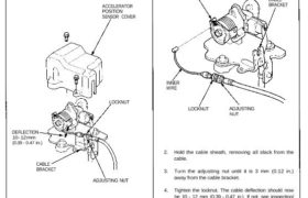
Intake Air System Throttle Cable Inspection/Adjustment 1. Remove the accelerator position sensor cover. 2. Check that the throttle cable operates smoothly with no binding or sticking. Repair as necessary. 3. Check cable free play at the throttle linkage. Cable deflection should be 10 – 12 mm (0.39 – 0.47 in.). ACCELERATOR POSITION SENSOR COVER DEFLECTION […]
Categories
nsxd11084a.pdf
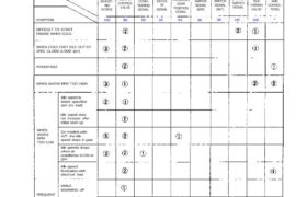
Idle Control System System Troubleshooting Guide NOTE: Across each row in the chart, the sub-systems that could be sources of a symptom are ranked in the order they should be inspected, starting with . Find the symptom in the left column, read across to the most likely source, then refer to the page listed at […]
Categories
nsxd11140a.pdf
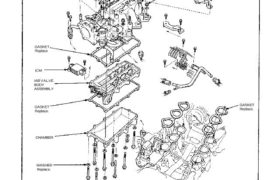
Intake Air System Intake Air Bypass (IAB) Control System (cont’d) Disassembly 22 N.m (2.2 kg-m, 16 Ib-ft) INTAKE MANIFOLD 22 N.m (2.2 kg-m. 16 Ib-ft) GASKET Replace. WASHER Replace. 22 N.m (2.2 kg-m, 16 Ib-ft) GASKET Replace. CHAMBER ICM IAB VALVE BODY ASSEMBLY GASKET Replace Attachments nsxd11140a (194 kB)
Categories
nsxd11040a.pdf
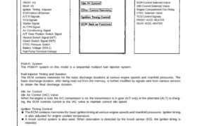
PGM-FI System System Description INPUTS ENGINE CONTROL MODULE (ECM) OUTPUTS FRONT HO2S REAR HO2S MAP Sensor CKP/CYP Sensor ECT Sensor TP Sensor IAT Sensor VSS FRONT KS REAR KS Ignition Timing Adjuster EGR Valve Lift Sensor A/T Fl Signals TCS Signals Starter Signal ALT FR Signal Air Conditioning Signal A/T Gear Position Switch Signal Neutral […]
Categories
nsxb11052a.pdf
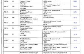
These DTCs will be indicated by the blinking of the Malfunction Indicator Lamp (MIL) with the SCS service connector connected Troubleshooting Diagnostic Trouble Code (DTC) Chart 11-65 11-67 11-69 11-70 11-71 11-72 11-73 11-74 11-75 11-77 11-78 11-80 11-81 11-85 11-82 11-83 11-84 11-85 11-78 11-80 11-81 11-85 11-82 11-83 11-84 11-85 11-87 11-87 Main […]
Categories
nsxd11032a.pdf
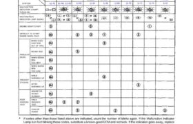
Troubleshooting Troubleshooting Guide NOTE: Across each row in the chart, the systems that could be sources of a symptom are ranked in the order they should be inspected starting with . Find the symptom in the left column, read across to the most likely source, then refer to the page listed at the top of […]
Categories
nsxb11157a.pdf
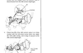
Intake Air Bypass (IAB) Control Valve Testing CAUTION: Do not adjust the IAB control valve full-close screw. It was preset at the factory. 1. Check the IAB control valve shaft for binding or sticking. 2. Check the IAB control valve for smooth movement. 3. Check that of the IAB control valve is in close contact […]
Categories
nsxe11026a.pdf
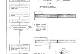
PGM-FI Control System Troubleshooting Flowchart ECU Check Engine light never comes on (even for two seconds) after ignition is turned on. Is the oil pressure light on? Turn the ignition switch OFF. Inspect No. 5 fuse. Is No. 5 fuse OK? Replace fuse. Connect the ECU test harness between the ECU and connector (page 11-21). […]
Categories
nsxb11130a.pdf
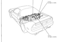
Fuel Supply System Fuel Lines NOTE: Check all fuel system lines and hoses for damage, leaks or deterioration, and replace if necessary. 27 N-m (2.8 kgf-m, 21 Ibf-ft) 27 N-m (2.8 kgf-m, 21 Ibf-ft) 27 N-m (2.8 kgf-m, 21 Ibf-ft) 22 N-m (2.2 kgf-m, 16 Ibf-ft) NOTE: Check all hose clamps and retighten if necessary. […]
Categories
nsxe11106a.pdf
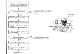
Fuel Supply System Fuel Pump Resistor Troubleshooting Flowchart Engine will not start. Inspection of fuel pump resistor. Disconnect the fuel pump resis- tor connector. Measure the voltage between BLK/YEL (+) (on harness side) and body ground (-) when the ig- nition switch is first turned ON. Is there battery voltage? (for 2 seconds) Inspect the […]