Category: Fuel & Emissions
nsxb11138a.pdf
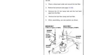
Fuel Supply System Fuel Filter Do not smoke while working on fuel sys- tem. Keep open flame away from your work area. The fuel filter should be replaced every 4 years or 60,000 miles (96,000 km), whichever comes first, or whenever the fuel pressure drops below the specified value [324 – 363 kPa (3.3 – […]
nsxd11128a.pdf
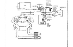
Intake Air System System Description The system supplies air for all engine needs. It consists of the intake air pipe. Air Cleaner (ACL), intake air duct, throttle body. Idle Air Control (IAC) Valve, fast idle thermo valve, and intake manifold. A resonator in the intake air duct provides additional silencing as air is drawn into […]
nsxd11157a.pdf
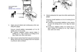
Evaporative Emission (EVAP) Two Way Valve Testing 1. Remove the fuel fill cap. 2. Remove vapor line from the fuel tank and connect to T-fitting from vacuum gauge and vacuum pump as shown. PRESSURE SIDE 3. Apply vacuum slowly and continuously while wat- ching the gauge. Vacuum should stabilize momentarily at 5 to 15 mmHg […]
nsxe11125a.pdf
System Description Tailpipe Emission The emission control system includes a three-way catalytic converter, exhaust gas recirculation (EGR) system, crankcase ventilation system and evaporative control system. The emission control system is designed to meet federal and state emission standards. Inspection Do not smoke during this procedure. Keep any open flame away from your work area. 1. […]
nsxe11024a.pdf
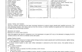
PGM-FI Control System System Description INPUTS ELECTRONIC CONTROL UNIT OUTPUTS CRANK/CYL Sensors MAP Sensor TW Sensor TA Sensor Throttle Angle Sensor Oxygen Sensors EGR Valve Lift Sensor Vehicle Speed Sensor Ignition Timing Adjuster Knock Sensers A/T Fl Signals TCS Signals Starter Signal Alternator FR Signal Air Conditioning Signal A/T Shift Position Signal M/T Neutral Switch […]
nsxe11074a.pdf
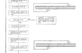
Idle Control System Troubleshooting Flowchart Alternator FR Signal This signals the PGM-FI ECU when the alternator is charging. Inspection of Alternator FR signal. Connect the ECU test harness between the ECU and connector. Disconnect “D” connector from the engine wire harness only, not the ECU (page 11-21). Turn the ignition switch ON. Measure voltage between […]
nsxd11113a.pdf
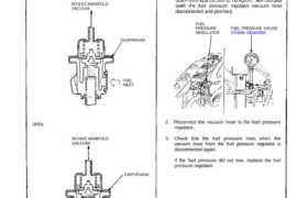
Fuel Pressure Regulator Description The fuel pressure regulator maintains a constant fuel pressure to the fuel injectors. When the difference be- tween the fuel pressure and manifold pressure exceeds 3.5 kg/cm2 (50 psi), the diaphragm is pushed upward, and the excess fuel is fed back into the fuel tank through the fuel return pipe. CLOSE […]
nsxb11142a.pdf
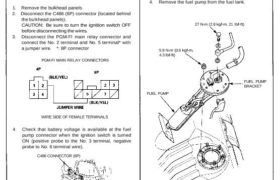
Fuel Supply System Fuel Pump Testing Do not smoke during the test. Keep open flame away from your work area. If you suspect a problem with the fuel pump, check that the fuel pump actually runs. When it is ON, you will hear some noise if you hold your ear to the fuel fill port […]
nsxb11139a.pdf
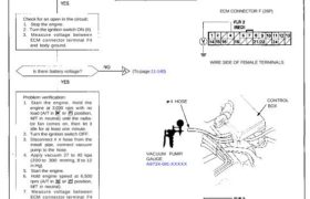
Fuel Pump Relay Troubleshooting Flowchart Inspection of fuel pump relay. Turn the ignition switch to START (III) position. Does the engine start? Check for an open in the circuit: 1. Stop the engine. 2. Turn the ignition switch ON (II). 3. Measure voltage between ECM connector terminal F4 and body ground. Is there battery voltage? […]
nsxd11114a.pdf
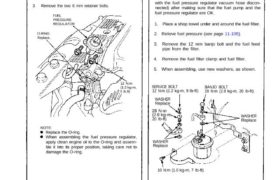
Fuel Supply System Fuel Pressure Regulator (cont’d) Replacement Do not smoke while working on fuel Fuel Filter Replacement Do not smoke while working on fuel The fuel fitter should be replaced: every 4 years or 60,000 miles (96,000 km), whichever comes first or whenever the fuel pressure drops below the specified value (330-370 kPa (3.30-3.70 […]