System Description
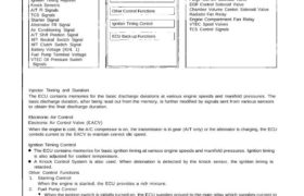
INPUTS ELECTRONIC CONTROL UNIT OUTPUTS
CRANK/CYL Sensors
MAP Sensor
TW Sensor
TA Sensor
Throttle Angle Sensor
Oxygen Sensors
EGR Valve Lift Sensor
Vehicle Speed Sensor
Ignition Timing Adjuster
Knock Sensers
A/T Fl Signals
TCS Signals
Starter Signal
Alternator FR Signal
Air Conditioning Signal
A/T Shift Position Signal
M/T Neutral Switch Signal
M/T Clutch Switch Signal
Battery Voltage (IGN. 1)
Fuel Pump Terminal Voltage
VTEC Oil Pressure Switch
Signals
Injector Timing and Duration
Electronic Idle Control
Other Control Functions
Ignition Timing Control
ECU Back-up Functions
Injectors
Main Relay (Fuel Pump)
Fuel Pump Relay
Check Engine Light
EACV
A/C Compressor Clutch Relay
Igniter Unit
Purge Cut-Off Solenoid Valve
EGR Control Solenoid Valve
Chamber Volume Control Solenoid Valve
Radiator Fan Relay
Engine Compartment Fan Relay
VTEC Spool Valves
TCS Control Signals
Injector Tinning and Duration
The ECU contains memories for the basic discharge durations at various engine speeds and manifold pressures. The
basic discharge duration, after being read out from the memory, is further modified by signals sent from various sensors
to obtain the final discharge duration.
Electronic Air Control
Electronic Air Control Valve (EACV)
When the engine is cold, the A/C compressor is on, the transmission is in gear (A/T only) or the alternator is charging, the ECU
controls current to the EACV to maintain correct idle speed.
Ignition Timing Control
The ECU contains memories for basic ignition timing at various engine speeds and manifold pressures. Ignition timing
is also adjusted for coolant temperature.
A Knock Control System is also used. When detonation is detected by the knock sensor, the ignition timing is
retarded.
Other Control Functions
1. Starting Control
When the engine is started, the ECU provides a rich mixture.
2. Fuel Pump Control
When the ignition switch is initially turned on, the ECU supplies ground to the main relay which supplies current to
the fuel pump for two seconds to pressurize the fuel system.
When the engine is running, the ECU supplies ground to the mam relay which supplies current to the fuel pump.
When the engine is not running and the ignition is on, the ECU cuts ground to the main relay which cuts current
to the fuel pump.
Excellent engine performance is achieved through the use of VTEC (Variable Valve Timing and Lift Electronic Con-
trol System), intake manifold chamber control and discharge volume control of the fuel pump.
3. Fuel Cut-of f Control
During deceleration with the throttle valve closed, current to the injectors is cut off to improve fuel economy at
speeds over 1,500 rpm.
Fuel cut-off action also takes place when engine speed exceeds, 8,300 rpm, regardless of the position of the
throttle valve, to protect the engine from over-revving.
4. A/C Compressor Clutch Relay
When the ECU receives a demand for cooling from the air conditioning system (compressor control unit), it delays
the compressor from being energized, and enriches the mixture to assure smooth transition to the A/C mode.
5. Purge Cut-off Solenoid Valve
When the coolant temperature is below 70 °C (158 °F), the ECU supplies a ground to the purge cut-off solenoid valve
which cuts vacuum to the purge control valve.
6. Chamber Volume Control Solenoid Valve (CVCSV)
When the engine rpm is below 4,800 rpm the CVCSV is activated by a signal from the ECU, intake air flows through
a smaller chamber, then high torque is delivered. At speeds higher than 4,800 rpm, both solenoid valves are deac-
tivated by the ECU, and intake air flows through the a larger chamber in order to increase airflow.
7. EGR Control Solenoid Valve (EGR CSV)
When the EGR is required for control of oxides of nitrogen (NOx) emissions, the ECU supplies ground to the EGR CSV
which supplies regulated vacuum to the EGR valve.
ECU Back-up Functions
1. Fail-Safe Function
When an abnormality occurs in a signal from a sensor, the ECU ignores that signal and assumes a pre-programmed
value that allows the engine to continue to run.
2. Back-up Function
When an abnormality occurs in the ECU itself, the injectors are controlled by a back-up circuit independent of the
system in order to permit minimal diving.
3. Self-diagnosis Function (Check Engine light)
When an abnormality occurs in a signal from a sensor, the ECU lights the Check Engine light and stores the failure
code in erasable memory. When the ignition is initially turned on, the ECU supplies ground for the Check Engine light
for two seconds.