Category: Fuel & Emissions
nsxe11067a.pdf
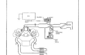
System Description The idle speed of the engine is controlled by the Electronic Air Control Valve (EACV). The valve changes the amount of air bypassing into the intake manifold in response to electric current sent from the ECU. When the EACV is activated, the valve opens to maintain the proper idle speed. BLU/RED EACV ECU […]
nsxb11046a.pdf
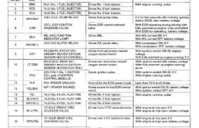
Troubleshooting Engine Control Module Terminal Arrangement ECM CONNECTOR A (26P) ECM CONNECTOR A (26P) TERMINAL SIDE OF MALE TERMINALS NOTE: Standard battery voltage is 12 V. ECM CONNECTOR B (16P) ECM CONNECTOR B (16P) TERMINAL SIDE OF MALE TERMINALS NOTE: Standard battery voltage is 12 V. *: M/T Main Menu Table of Contents O 1 […]
nsxb11149a.pdf
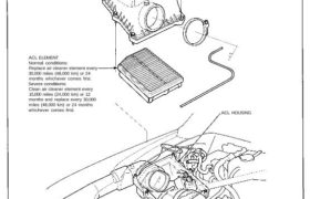
Air Cleaner (ACL) ACL Element Replacement ACL HOUSING COVER ACL ELEMENT Normal conditions: Replace air cleaner element every 30,000 miles (48,000 km) or 24 months whichever comes first. Severe conditions: Clean air cleaner element every 15,000 miles (24,000 km) or 12 months and replace every 30,000 miles (48,000 km) or 24 months whichever comes first. […]
nsxd11130a.pdf
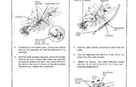
Intake Air System Inspection/Adjustment 1. Warm up the engine to normal operating tem- perature (the cooling fan comes on). 2. Check that the throttle cable operates smoothly with no binding or sticking. Repair as necessary. 3. Check cable free play at the throttle linkage. Cable deflection should be 10—12 mm (0.39—0.47 in.). Installation 1. Fully […]
nsxb11028a.pdf
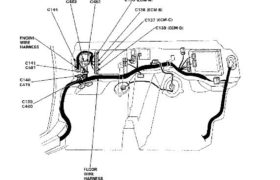
System Description System Connectors [Behind the bulkhead panels] Main Menu Table of Contents System Description System Connectors [Behind the bulkhead panels] icont’d) C483 c482 c135 (ECM-A) C144 C136 (BOMB) C137 (ECM-C) C1 38 (ECM-DI ENGINE WIRE HARNESS C141 ì i C481 c140 c479 Í C139 j I C480 /1 у / FLOOR WIRE HARNESS 11-28 […]
nsxd11101a.pdf
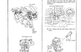
Fast Idle Thermo Valve Description To prevent erratic running when the engine is warming up, it is necessary to raise the idle speed. The fast idle thermo valve is controlled by a thermowax plunger. When the engine is cold, the engine coolant surround- ing the thermowax contracts the plunger, allowing ad- ditional air to be […]
nsxe11114a.pdf
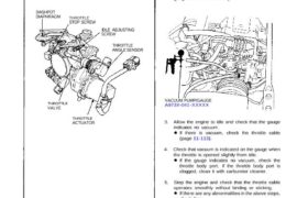
Air Intake System Throttle Body Description The throttle body is of the single-barrel side-draft type. The lower portion of the throttle valve is heated by engine coolant which is fed from the cylinder head. The idle adjusting screw which increases/decreases bypass air and the canister/purge port are located on the top of the throttle body. […]
nsxd11022a.pdf
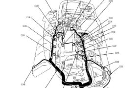
System Description System Connecors [Engine Compartment (Right Side)] (cont’d) C132 C171 C130 C133 KNOCK SENSOR HARNESS C143 C173 C172 C141 C139 C140 C138 C101 C137 C146 C144 C152 C151 C149 C142 ENGINE WIRE HARNESS C148 C136 C135 C134 C130 C132 C133 C134 C135 C136 C137 C138 C139 C140 C141 C142 C143 C144 C146 C148 C149 […]
nsxd11104a.pdf
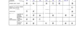
Fuel Supply System System Troubleshooting Guide NOTE: Across each row in the chart, the sub-systems that could be sources of a symptom are ranked in the order they should be inspected starting with . Find the symptom in the left column, read across to the most likely source, then refer to the page listed at […]
nsxd11092a.pdf
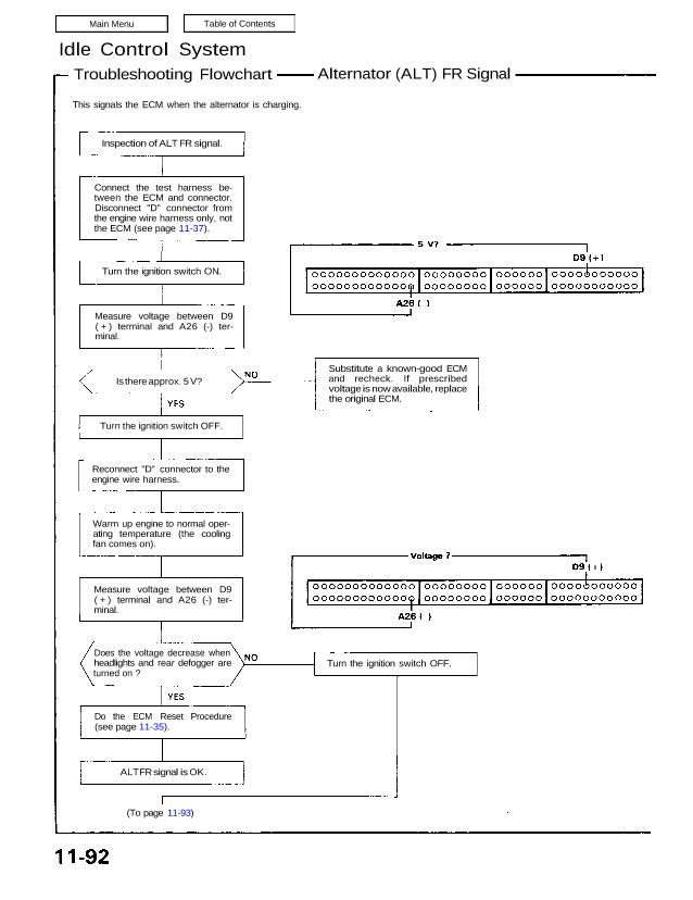
Idle Control System Troubleshooting Flowchart Alternator (ALT) FR Signal This signals the ECM when the alternator is charging. Inspection of ALT FR signal. Connect the test harness be- tween the ECM and connector. Disconnect “D” connector from the engine wire harness only, not the ECM (see page 11-37). Turn the ignition switch ON. Measure voltage […]