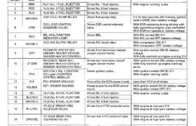
Engine Control Module Terminal Arrangement
ECM CONNECTOR A (26P)
ECM CONNECTOR A (26P)
TERMINAL SIDE OF MALE TERMINALS
NOTE: Standard battery voltage is 12 V.
ECM CONNECTOR B (16P)
ECM CONNECTOR B (16P)
TERMINAL SIDE OF MALE TERMINALS
NOTE: Standard battery voltage is 12 V.
*: M/T
Main Menu
Table of Contents
O 1
IGN GN
COIL5
ECM CONNECTOR B (16P)
1
l
CO
ECM CONNECTOR B (16Р)
15
CVP 2M CVP 1M CKP ZM
TERMINAL SIDE OF MALE TERMINALS
NOTE: Standard battery voltage is 12 V.
⋆∶ MIT
Terminal Wire . . . .
number colo, Terminal name Description 5.9|13|
VTP SWR (FRONT VTEC Detects VTEC pressure switch With engine at low rpm: O V
1 BLU PRESSURE SWITCH) signal. With engine at high rpm:
battery voltage
↴ IGN COILB (No. 6 IGNITION Sends ignition pulse. With ignition switch ON (II): 0 V
2 RED COIL part of IGNITION With engine running: pulse
CONTROL MODULE)
VTP SWR (REAR VTEC Detects VTEC pressure switch With engine at low rpm: 0 V
3 BLU/BLK PRESSURE SWITCH) signal. With engine at high rpm:
battery voltage
4 RED ATP PN (А/Т GEAR Detects AfI’ gear position In Ш] or IE] position: 0 V
POSITION SWITCH) switch signal. In any other position: approx. 5 V
4* LT GRN NT SW (NEUTRAL Detects neutral switch signal. In neutral position: O V
SWITCH) In any other position: approx. 5 V
CYP 2P (CYP SENSOR 2 P Detects CYP sensor 2. With engine running: pulse
5 ORN SIDE)
CYP ‘IF’ (CYP SENSOR 1 P Detects CYP sensor 1. With engine running: pulse
6 WHT ↴
SIDE)
−∣ CRN/BLU ÉIÉPEÏP (CKP SENSOR 2 P Detects CKP sensor 2. With engine running: pulse
8 BLU/GRN (82:(DPE;P (CKP SENSOR 1 P Detects CKP sensor 1. WIth engine running: pulse
g BRN/BLK LG2 (LOGIC GROUND) ::Staind for the ECM control Less than 1.0 V at all times
IGN COILS (No. 5 IGNITION Sends ignition pulse. With ignition switch ON (II): 0 V
10 GRY COIL part of IGNITION With engine running: pulse
CONTROL MODULE)
IGN COIL4 (No. 4 IGNITION Sends ignition pulse. With ignition switch ON (II): O V
11 GRN COIL part of IGNITION With engine running: pulse
CONTROL MODULE)
IGN COIL3 (No. 3 IGNITION Sends ignition pulse. With ignition switch ON (II): 0 V
12 BLU COIL part of IGNITION With engine running: pulse
CONTROL MODULE)
13 GRN/BLU CYP 2M (CYP SENSOR 2 M I Ground for CYP sensor 2.
SIDE)
14 WHT/BLU CYP 1M (CYP SENSOR 1 M Ground for CYP sensor 1.
SIDE)
↱
15 WHT/BLU CKP 2M (CKP SENSOR 2 M Ground for CKP sensor 2.
SIDE)
16 BLIJ/VEL (SÌÉPE3M (CKP SENSOR 1 M Ground for CKP sensor 1.
(co nt‘d)
11-47
Troubleshooting
Engine Control Module Terminal Arrangement (cont’d)
ECM CONNECTOR C (12P)
TERMINAL SIDE OF MALE TERMINALS
ECM CONNECTOR C (12P) NOTE: Standard battery voltage is 12 V.
*: M/T
ECM CONNECTOR 0 (22P)
ECM CONNECTOR D (22P)
TERMINAL SIDE OF MALE TERMINALS
NOTE: Standard battery voltage is 12 V.
Main Menu
Table of Contents
ECM CONNECTOR 0 (22P)
TERMINAL SIDE OF MALE TERMINALS
ECM CONNECTOR D (ZZP) NOTE: Standard battery voltage is 12 V.
Terminal Wire I . . . .
number color Terminal name Descrlptlon Signal
VBU (VOLTAGE BACK UP] Power source for the ECM con- Battery voltage at all times
1 WHT/VEL troI circuit,
1 ⇝ ∙ V ⋡ Power source for the DTC memory ⋮
2 RED/BLU ËÊîJiREAR KNOCK SENSOR Detects knock sensor signal, With engine knocking: pulse
т РРЗИЛЁУАР PURGE Detects EVAP purge flow switch With engine at 2,000 -EJOO rpm: О \/ 7—
3 BRN SWITCH) signal. With engine above or below except
2,000 — 2,700 rpm: battery voltage
K-LINE (DLC) Sends or detects PGM tester and With ignition switch ON (II): about 5 V
4 YEL/GRN .
OBD II scan tool signal,
5 WHT/RED ALTF (ALTERNATOR FR SIG- Detects alternator FR signal. With fully warmed up engine running:
NAL) 0 V — 5 V (depending on electrical load)
ЕСТ (ENGINE COOLANT TEM« Detects ECT sensor signal. With ignition switch ON (II): about
7 RED/WHT PERATURE SENSOR) 0174.8 V (depending on engine coolant
Ä W W ∙ 7 ⋝↣ ⊲ v temperature)
IAT (INTAKE AIR TEMPERAV Detects IAT sensor signal. With ignition switch ON (II): about
В RED/VEL TURE SENSOR) 0.1 -4.8 V (depending on intake air tem—
peratura)
MAP (MANIFOLD ABSOLUTE Detects MAP sensor signal. With ignition switch ON (II): about 3 V
Э WHT/YEL PRESSURE SENSOR) During idling: about 1.0 V (depending on
engine speed)
_Io VEL/BLU VCC2 (SENSOR VOLTAGE) Provides sensor voltage. With ignition switch ON (Il): about 5 V
With ignition switch OFF: O V
11 GRN/BLU SGZ (SENSOR GROUND) Sensor ground.
TPS (THROTTLE POSITION Detects TP sensor signal. With throttle fully open: about 4.5 V
12 RED/BLK SENSOR) With throttle fully closed with fully
warmed up engine: about 0.5 V
KSF (FRONT KNOCK SENSOR Detects knock sensor signal. With engine knocking: pulse
13 WHT K52]
02$ FS (FRONT SECONDARY Detects secondary oxygen sen- With throttle fully opened with fully
16 GRN OXYGEN SENSOR) sor signal. warmed up engine: above 0.6 V
With throttle quickly closed: below 0.4 V
OZS RS (REAR SECONDARY Detects secondary oxygen sen» With throttle fully opened with fully
17 WHT/RED OXYGEN SENSOR) sor signal. warmed up engine: above 0.6 V
g _A N i i With throttle quickly closed: below 0.4
OZS FF (FRONT PRIMARY Detects primary oxygen sensor With throttle fully opened with fully
1B BLU/RED OXYGEN SENSOR) signal. warmed up engine: above 0.6 V
With throttle quickly closed: below 0.4 V
025 RP (REAR PRIMARY OXY— Detects primary oxygen sensor With throttle fully opened with fully
19 WHT GEN SENSOR) signal. warmed up engine: above 0.6 V
‘ With throttle quickly closed: below 0.4 V
EGRL (EGR VALVE LIFT SEN— Detects EGR valve lift sensor During idling without vacuum: about 1.2 V
20 WHT/BLK ЗОН) signal. With 27 kPa (200 mmHg, 8 in.Hg): about
4.3 V
i OZS’GNOES (FRONT SEC- Sensor ground for front sec- т
21 BLU/GRN I ONDARY OXYGEN SENSOR ondary oxygen sensor.
GROUND)
OZSGND RS (REAR SEO Sensor ground for rear sec-
22 WHT 0NDARY OXYGEN SENSOR ondarv oxygen sensor.
GROUND)
(co nt’d)
11-49
Troubleshooting
Engine Control Module Terminal Arrangement (cont’d)
ECM CONNECTOR F (26P)
ECM CONNECTOR F (26P)
TERMINAL SIDE OF MALE TERMINALS
NOTE: Standard battery voltage is 12 V.
*: M/T
ECM CONNECTOR G (12P)
ECM CONNECTOR G (12P)
TERMINAL SIDE OF MALE TERMINALS
NOTE: Standard battery voltage is 12 V.
Main Menu
Table of Contents
ECM CONNECTOR G (12P)
TERMINAL SIDE OF MALE TERMINALS
ECM CONNECTOR G (12P)
NOTE: Standard battery voltage is 12 V.
Terminal
Wire
Terminal name Description Signal
number color
IGM1 (POWER SOURCE) Power source for throttle With ignition switch ON (II):
2 GRN/RED valve control motor. battery voltage
With ignition switch OFF: 0 V
IGM2 (POWER SOURCE) Power source for throttle With ignition switch ON (ll):
3 GRN/RED valve control motor. battery voltage
With ignition switch OFF: 0 V
PM‘l (MOTOR PHASE Sends pulse to throttle valve With ignition switch ON (Il): 0 V or
4 BRN OUT 1) control motor. pulse
With ignition switch OFF: 0 V
PM2 (MOTOR PHASE Sends pulse to throttle valve With ignition switch ON (II): O V or
5 WHT/GRN OUT 2) control motor. pulse
With ignition switch OFF: O V
7 BLK PGM1 (POWER GROUND) Power ground for throttle
valve control motor.
8 BLK PGMZ (POWER GROUND) Power ground for throttle
valve control motor.
COM1 (COMMON POWER Sends power source to With ignition switch ON (II): pulse
9 ORN SOURCE FOR MOTOR throttle valve control motor. With ignition switch OFF: 0 V
PHASE 1 and 3)
COMŻ (COMMON POWER Sends power source to With ignition switch ON (II): pulse
10 GRN SOURCE FOR MOTOR throttle valve control motor. With ignition switch OFF: 0 V
PHASE 2 and 4)
PM3 (MOTOR PHASE Sends pulse to throttle valve With ignition switch ON (II): 0 V or
11 YEL OUT 3) control motor. pulse
With ignition switch OFF: O V
PM4 (MOTOR PHASE Sends pulse to throttle valve With ignition switch ON (Il): 0 V or
12 RED OUT 4) control motor. pulse
With ignition switch OFF: 0 V
11-51