Category: Electrical
Categories
nsxb23300a.pdf
Cruise Control Description The cruise control system uses mechanically and electri- cally operated devices to maintain vehicle speed at a setting selected by the driver. The ECM receives command signals from the cruise con- trol main switch and the cruise control set/resume switch. It receives information about operating conditions from the brake switch, vehicle speed […]
Categories
nsxe23279a.pdf
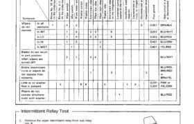
Troubleshooting NOTE: The numbers in the table show the troubleshooting sequence. Intermittent Relay Test 1. Remove the wiper intermittent relay from sub relay box B. 2. There should be continuity between the A and C ter- minals when the battery is connected to the E and F terminals. The should be continuity between the B […]
Categories
nsxb23072a.pdf
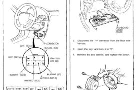
Ignition Switch Test 1. Remove the dashboard lower cover (see next column). 2. Disconnect the 7-P connector from the floor wire harness. 3. Check for continuity between the terminals in each switch position according to the table. WHT (BAT-A) BLU/WHT (IG2-B) View from wire side BLK/WHT (ST) WHT/BLK (BAT-B) WHT/RED (ACC) Electrical Switch Replacement 1. […]
Categories
nsxd23256a.pdf
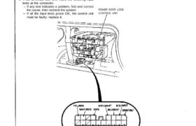
Power Door Locks Control Unit Input Test Remove the glove box, then disconnect the 18-P con- nector from the control unit. Inspect the connector terminals to be sure they are all making good contact. If the terminals are bent, loose, or corroded, repair them as necessary, and recheck the system. If the terminals look OK, […]
Categories
nsxd23179a.pdf
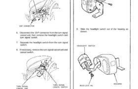
5. Remove the four screws from the headlight switch. HEADLIGHT SWITCH 10-P CONNECTOR 16-P CONNECTOR 6. Disconnect the 10-P connector from the turn signal cancel unit, then remove the headlight switch and turn signal switch. 7. Separate the headlight switch from the turn signal switch. 8. If necessary, remove the turn signal cancel unit and […]
Categories
nsxb23081a.pdf
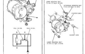
Starter Solenoid Test 1. Check the hold-in coil for continuity between the S terminal and the armature housing (ground). The coil is OK if there is continuity. ARMATURE HOUSING (GROUND) PULL – IN COIL HOLD – IN COIL 2. Check the pull-in coil for continuity between the S and M terminals. The coil is OK […]
Categories
nsxb23289a.pdf
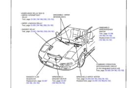
Wipers/Washers Component Location Index SRS components are located in this area. Review the SRS component locations, precautions, and procedures in the SRS section (24) before performing repairs or ser- vice. UNDER-HOOD RELAY BOX B WIPER INTERMITTENT RELAY Test, page 23-291 (’94-’96) (’93) (’91-’92) WIPER LOW/HIGH RELAY Test, page 23-292 (’94-’96) (’93) (’91-’92) WASHER RELAY Test, […]
Categories
nsxb23244a.pdf
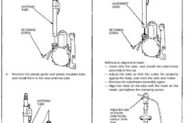
Stereo Sound System Antenna Tube Replacement 1. Remove the antenna mast (see page 23-242). 2. Remove the power antenna motor (see page 23-242). 3. Remove the retaining screw, and pull the antenna tube out of its socket in the drive housing. ANTENNA TUBE RETAINING SCREW 4. Remove the plastic guide and plastic insulator tube, and […]
Categories
nsxb23185a.pdf
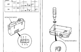
Retractor Switch Test 1. Remove the retractor switch (see previous page). 2. Check for continuity between the terminals in each switch position according to the table. Retractor Switch RETRACTOR SWITCH Retractor Switch Retractor Switch Light Bulb Replacement 1. Remove the retractor switch (see previous page). 2. Turn the bulb 45° counterclockwise to remove it. RETRACTOR […]
Categories
nsxb23254a.pdf
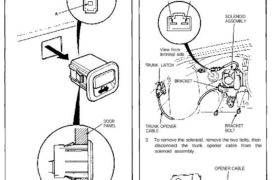
Trunk Opener Opener Switch Test 1. Remove the driver’s door panel, then push the switch out of the door panel as shown. 2. Check for continuity between the terminals. • There should be continuity between the A and B terminals when the switch is pushed. • There should be no continuity when the switch is […]