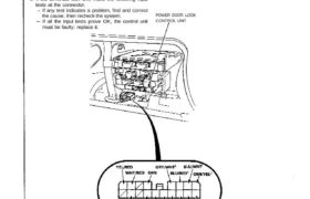
Control Unit Input Test
Remove the glove box, then disconnect the 18-P con-
nector from the control unit.
Inspect the connector terminals to be sure they are all
making good contact.
If the terminals are bent, loose, or corroded, repair
them as necessary, and recheck the system.
If the terminals look OK, make the following input
tests at the connector.
If any test indicates a problem, find and correct
the cause, then recheck the system.
If all the input tests prove OK, the control unit
must be faulty; replace it.
POWER DOOR LOCK
CONTROL UNIT
View from wire side
No.
1
2
3
4
5
6
7
8
9
Wire
BLK
ORN
GRN/WHT2
WHT/YEL
BLK/WHT
BLK/RED
BLU/WHT
BLU/RED1
GRY/WHT
GRN/YEL2
GRN/BLU
GRN/RED
BLU/GRN
WHT/RED
and
YEL/RED
Test condition
Under all conditions.
Under all conditions.
Driver’s door lock
switch in LOCK.
Driver’s door lock
switch in UNLOCK.
Passenger’s door lock
switch in LOCK.
Passenger’s door lock
switch in UNLOCK.
Driver’s door lock knob
in LOCK.
Driver’s door lock knob
in UNLOCK.
Passenger’s door lock
key cylinder switch in
LOCK.
Passenger’s door lock
key cylinder switch in
UNLOCK.
Driver’s door open.
Passenger’s door
open.
Ignition key is inserted
into the ignition switch.
Connect the ORN termi-
nal to the WHT/RED ter-
minal, and the YEL/RED
terminal to the BLK ter-
minal momentarily.
Connect the ORN ter-
minal to the YEL/RED
terminal, and the
WHT/RED terminal to
the BLK terminal
momentarily.
Test: Desired result
Check for continuity to
ground: There should be
continuity.
Check for voltage to ground:
There should be battery
voltage.
Check for voltage to ground:
There should be 1 V or less.
Check for voltage to ground:
There should be 1 V or less.
Check for voltage to ground:
There should be 1 V or less.
Check for voltage to ground:
There should be 1 V or less.
Check for voltage to ground:
There should be 1 V or less.
Check for voltage to ground:
There should be 1 V or less.
Check door lock operation:
Both doors should lock as
power and ground are con-
nected momentarily.
Check door lock operation:
Both doors should unlock as
power and ground are con-
nected momentarily.
Possible cause if result is not obtained
Poor ground (G401, 402)
An open in the wire.
Blown No. 35 (20A) fuse.
An open in the wire.
Faulty driver’s door lock switch.
Poor ground (G401, 402).
An open in the wire.
Faulty passenger’s door lock
switch.
Poor ground (G401, 402).
An open in the wire.
Faulty driver’s door lock actuator.
Poor ground (G401, 402).
An open in the wire.
Faulty passenger’s door lock
actuator.
Poor ground (G401, G402).
An open in the wire.
Faulty door switch.
Poor ground (G401, G402).
An open in the wire.
Faulty ignition key switch.
Poor ground (G401, 402).
An open in the wire.
Faulty actuator.
An open in the wire.
CAUTION: To prevent damage to the motor, connect power and ground only momentarily.