Troubleshooting Flowchart Engine Control Module (ECM) (cont’d)
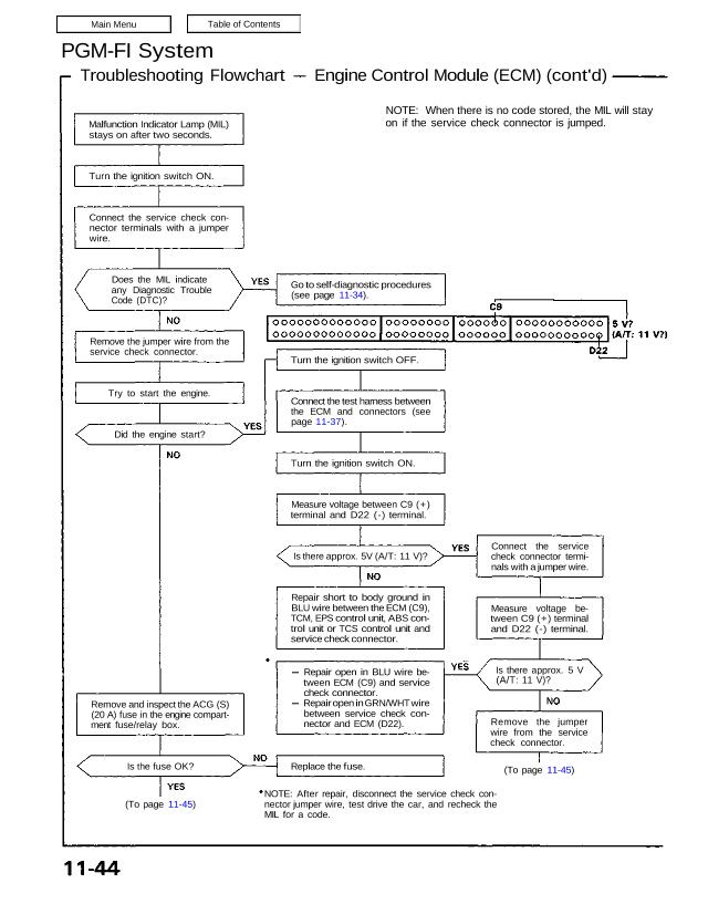
Malfunction Indicator Lamp (MIL)
stays on after two seconds.
Turn the ignition switch ON.
Connect the service check con-
nector terminals with a jumper
wire.
Does the MIL indicate
any Diagnostic Trouble
Code (DTC)?
Remove the jumper wire from the
service check connector.
Try to start the engine.
Did the engine start?
Remove and inspect the ACG (S)
(20 A) fuse in the engine compart-
ment fuse/relay box.
Is the fuse OK?
(To page 11-45)
Go to self-diagnostic procedures
(see page 11-34).
Turn the ignition switch OFF.
Connect the test harness between
the ECM and connectors (see
page 11-37).
Turn the ignition switch ON.
Measure voltage between C9 (+)
terminal and D22 (-) terminal.
Is there approx. 5V (A/T: 11 V)?
Repair short to body ground in
BLU wire between the ECM (C9),
TCM, EPS control unit, ABS con-
trol unit or TCS control unit and
service check connector.
Repair open in BLU wire be-
tween ECM (C9) and service
check connector.
Repair open in GRN/WHT wire
between service check con-
nector and ECM (D22).
Replace the fuse.
NOTE: After repair, disconnect the service check con-
nector jumper wire, test drive the car, and recheck the
MIL for a code.
NOTE: When there is no code stored, the MIL will stay
on if the service check connector is jumped.
Connect the service
check connector termi-
nals with a jumper wire.
Measure voltage be-
tween C9 (+) terminal
and D22 (-) terminal.
Is there approx. 5 V
(A/T: 11 V)?
Remove the jumper
wire from the service
check connector.
(To page 11-45)
(From page 11 -44)
Inspect the IG COIL (30 A) fuse
in the engine compartment
fuse/relay box.
Is the fuse OK?
Turn the ignition switch ON.
Disconnect the 3P connector of
each sensor one at a time:
MAP sensor
EGR valve lift sensor
Accelerator pedal angle sensor
Does the MIL remain ON?
Connect the service check con-
nector terminals with a jumper
wire.
Disconnect the 3P connector of
each sensor one at a time:
TP sensor
Ignition timing adjuster
Does the MIL indicate
code 7 or 18?
Turn the ignition switch OFF.
Remove the jumper wire from the
service check connector.
Connect the test harness.
Disconnect the “D” connector
from the ECM only, not the engine
wire harness (see page 11-37).
Check for continuity between
body ground and the following
terminals: D19, D20.
(To page 11-46)
Replace the fuse.
Substitute a known-good ECM
and recheck. If symptom/indica-
tion goes away, replace the origi-
nal ECM.
Replace the sensor that caused
the light to go out upon its discon-
nection.
Replace the TP sensor or ignition
timing adjuster.
(From page 11-44)
Turn the ignition switch
OFF.
Disconnect “A” con-
nector from the ECM.
Turn the ignition switch
ON.
Is the MIL on?
Repair short to body
ground in BLU wire be-
tween the ECM (A13)
and MIL.
Continuity?
(cont’d)
PGM-FI System
Troubleshooting Flowchart Engine Control Module (ECM) (cont’d)
(From page 11-45)
Is there continuity?
Reconnect all the connectors.
Reconnect the “D” connector to
the ECM.
Turn the ignition switch ON.
Measure voltage between body
ground and the following termi-
nals individually: A26, B2.
Is there less than 1.0 V?
Measure voltage between A26
(-) and the following: C1 (+) and
A25 ( + ).
Is there battery voltage?
Substitute a known-good ECM
and recheck. If symptom/indica-
tion goes away, replace the origi-
nal ECM.
Repair short to body ground in
YEL/WHT wire between ECM
(D19) and MAP sensor.
Repair short to body ground in
YEL/WHT wire between ECM
(O20) and TP sensor. EGR
valve life sensor, ignition tim-
ing adjuster or accelerator pe-
dal angle sensor.
Repair open in BRN/BLK (A26) or
BRN/WHT (B2) and G101 (locat-
ed at right middle of engine).
Repair open in YEL/BLK wire
between ECM (A25. CD and
PGM-FI main relay.
Check PGM-FI main relay and
wiring connectors at PGM-FI
main relay.