Adjustment
Valves should be adjusted cold when the cylinder head
temperature is less than 100°F (38°C).
Adjustment is the same for both intake and exhaust
valves.
Adjust valve clearance at TDC of each cylinder.
Do not rotate the engine counterclockwise. The tim-
ing belt could jump a tooth on the camshaft pulleys.
EXHAUST
INTAKE
INTAKE
EXHAUST
TDC MARK (WHITE PAINT)
CRANKSHAFT PULLEY
POINTER ON
THE LOWER
COVER
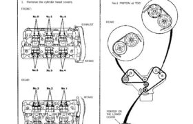
TDC mark (white paint) on the crank pulley should
align with pointer on the timing lower cover, and
TDC grooves on the camshaft pulleys should align
with timing belt cover plates.
FRONT:
No.1 PISTON at TDC
REAR:
NOTE:
1. Remove the cylinder head covers.
FRONT:
REAR:
2. Rotate crankshaft and set No.1 piston at TDC.
(cont’d)
LOCKNUT
7 x 0.75 mm
20 N.m (2.0 kg-m.
14 Ib-ft)
LOCKNUT
7 x 0.75 mm
20 N.m (2.0 kg-m.
14 Ib-ft)
EXHAUST:
6. Tighten locknut and check clearance again. Repeat
adjustment if necessary.
INTAKE:
3. Manually inspect the rocker arms for independent
operation (page 6-52, 53)
4. Adjust valves on No.1 cylinder.
TAPPET ADJUSTER
07MAA–PR70110
TAPPET LOCKNUT
WRENCH
07MAA–PR70120
EXHAUST:
NOTE: Use a mirror to check if the special tool is
positioned on the locknut correctly.
Adjusting screws are on primary and secondary
rocker arms.
Intake: 0.15-0.19 mm (0.006-0.007 in)
Exhaust: 0.17-0.21 mm (0.007-0.008 in)
5. Loosen locknut and turn adjustment screw until feel-
er gauge slides back and forth with slight amount
of drag.
INTAKE:
Valve Clearance
Adjustment (cont’d)
7. Rotate the crankshaft 120° clockwise (camshaft
pulley turns 60°). Check that the front intake cam-
shaft pulley is positioned as shown.
Repeat step 3 to step 6
Number 4 piston at TDC:
8. Rotate the crankshaft 120° clockwise (camshaft
pulley turns 60°). Check that the front intake cam-
shaft pulley is positioned as shown.
Repeat step 3 to step 6.
Number 2 piston at TDC:
9. Rotate the crankshaft 120° clockwise (camshaft
pulley turns 60°). Check that the front intake cam-
shaft pulley is positioned as shown.
Repeat step 3 to step 6.
Number 5 piston at TDC:
11. Rotate the crankshaft 120° clockwise (camshaft
pulley turns 60°). Check that the front intake cam-
shaft pulley is positioned as shown.
Repeat step 3 to step 6.
Number 6 piston at TDC:
10. Rotate the crankshaft 120° clockwise (camshaft
pulley turns 60°). Check that the front intake cam-
shaft pulley is positioned as shown.
Repeat step 3 to step 6.
Number 3 piston at TDC: