Function Test
NOTE:
• The ALB checker is designed to confirm proper
operation of the anti-lock brake system (ABS) by
simulating each system function and operating con-
dition. Before using the checker, confirm that the
anti-lock brake system (ABS) indicator light is not in-
dicating some other problem with the system. The
light should go on when the ignition is first turned on
and then go off and stay off one second after the
engine is started.
• The checker should be used through modes, 1-5, to
confirm proper operation of the system, in any one
of the following situations:
After replacing any ABS component.
After replacing or bleeding the system fluid (0
mode not necessary).
After any body or suspension repair that may
have affected the sensors or their wiring.
• The procedure for modes 1-5 are on this page and
19-42, mode 0 (wheel sensor signal) is on page
19-43.
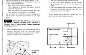
1. With the ignition switch off, disconnect the 6-P in-
spection connector from the connector cover
located under the glove box and connect the 6-P in-
spection connector to the ALB checker.
07HAJ-SG0010B
see page 19-2 for other applicable checkers.
NOTE: Place the vehicle on level ground with the
wheels blocked, put the transmission in neutral for
manual transmission models, and in for
automatic transmission models.
2. Start the engine and release the parking brake.
3. Operate the ALB checker as follows:
(1) Turn the Mode Selector switch to “1”.
(2) Push the Start Test switch:
— The test in progress light should come ON.
— In one or two more seconds, all four monitor
lights should come on (If not the checker is
faulty).
— The ABS indicator light should not come ON (If it
comes on the checker harness to the 6-P con-
nector connection is faulty).
NOTE: When test in progress indicator light ON,
don’t turn the Mode Selector switch.
ALB Checker
Function Test (cont’d)
4. Turn the Mode Selector switch further to “2”.
5. Depress the brake pedal firmly and push the Start
Test switch
The ABS indicator light should not go on while the
Test in Progress light is ON. There should be
kickback on the brake pedal. If not as described, go
to troubleshooting, page 19-44 (’91-’92) (’93-’96).
NOTE: The operation sequence simulated lby
Modes 2, 3, 4 and 5:
START About 30 seconds END
6. Turn the Mode Selector switch to 3, 4 and 5.
Perform step 5 for each of the test mode positions.
Mode 1:
Sends the simulated driving signal O mph (O km/h)
–> 113 mph (180 km/h) –> O mph (O km/h) of each
wheel to the ABS control unit. There should be NO
kickback.
Mode 2:
Sends the driving signal of each wheel, then sends
the lock signal of the rear left wheel to the ABS
control unit. There should be kickback.
Mode 3:
Sends the driving signal of each wheel, then sends
the lock signal of the rear right wheel to the ABS
control unit. There should be kickback.
Mode 4:
Sends the driving signal of each wheel, then sends
the lock signal of the front left wheel to the ABS
control unit. There should be kickback.
Mode 5:
Sends the driving signal of each wheel, then sends
the lock signal of the front right wheel to the ABS
control unit. There should be kickback.
NOTE: If little or no kickback is felt from the brake
pedal in modes 2 – 5, repeat the function test of
modes 1–5 several times before beginning to
troubleshoot other parts of the system.
Mode 6:
Not used on this model.
Inspection points:
1. The ABS indicator light goes ON in mode 1.
Check for DTCs, and refer to the appropriate
troubleshooting.
If ABS indicator light goes on 120 seconds later
but the pump motor stops, refer to page 19-47.
2. There is no kickback in modes 2 through 5.
Faulty pressure switch (remains closed)
Shorted wires
Faulty or disconnected pump motor connector
Faulty pump motor relay
3. Weak kickback in modes 2 through 5.
Bleed high pressure circuits.
4. Pump motor stops in mode 1, but it does not stop
and there is no kickback in modes 2 through 5.
Brake fluid leakage
Bleed power unit
Clogged power unit outlet
Clogged or deteriorated power unit hose