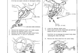
Steering Lock Replacement
SRS wire harness is routed near the steering lock
assembly.
CAUTION:
All SRS electrical wiring harnesses are covered with
yellow outer insulation.
Before disconnecting the SRS wire harness, install
the short connector on the airbag (see page 23-323).
Replace the entire affected SRS harness assembly
if it has an open circuit or damaged wiring.
CABLE REEL
SRS MAIN WIRE HARNESS
1. Remove the dashboard lower and center panels.
2. Remove the steering column covers.
3. Remove the knee bolster and dash lower frame.
4. Disconnect the 7-P and 6-P connectors.
DASH LOWER FRAME
KNEE BOLSTER (cont’d)
NOTE: The illustration shows A/T.
6. Lower the steering column assy.
7. Center punch each of the shear bolts and drill their
heads off with a 3/16 in. drill bit.
CAUTION: Do not damage the switch body when
removing the shear bolt head.
8. Remove the shear bolts from the switch body.
39 N·m
(3.9 kg-m, 28 Ib-ft)
16 N·m
(1.6 kg-m. 12 Ib-ft)
4. Remove the column holder mount bolts.
5. Remove the mounting nuts.
Ignition Switch
Steering Lock Replacement (cont’d)
9. Insert the key and turn it to “1”.
NOTE: The illustration shows A/T.
STEERING LOCK
BODY
LOCK PIN
10. Push the lock pin and pull out the steering lock as-
sembly.
TWIST-OFF PORTION
SHEAR BOLT
11. Turn the key to “1”, push the pin and insert the
steering lock assembly into the steering column
until it clicks into place.
12. Loosely tighten the new shear bolt.
NOTE: Make sure the projection on the ignition
switch is aligned with the hole in the steering
column.
13. Insert the ignition key and check for proper opera-
tion of the steering wheel lock and that ignition key
turns freely.
14. Tighten the shear bolt until the hex head twists off.