Reassembly
SHIFT LEVER
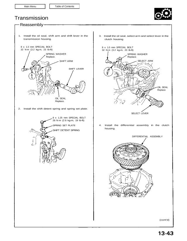
3. Install the oil seal, select arm and select lever in the
clutch housing.
OIL SEAL
Replace.
SELECT LEVER
4. Install the differential assembly in the clutch
housing.
DIFFERENTIAL ASSEMBLY
(cont’d)
1. Install the oil seal, shift arm and shift lever in the
transmission housing.
8 x 1.0 mm SPECIAL BOLT
32 N·m (3.2 kg-m, 23 Ib-ft)
SPRING WASHER
Replace.
SHIFT ARM
OIL SEAL
Replace.
2. Install the shift detent spring and spring set plate.
8 x 1.25 mm SPECIAL BOLT
26 N·m (2.6 kg-m, 19 Ib-ft)
SPRING SET PLATE
SHIFT DETENT SPRING
8 x 1.0 mm SPECIAL BOLT
32 N·m (3.2 kg-m, 23 Ib-ft)
SPRING WASHER
Replace.
SELECT ARM
Transmission
Reassenbly (cont’d)
5. Install the spring washer, then insert the mainshaft
and countershaft into the shift forks and install
them as an assembly.
NOTE: Tape the mainshaft spline, before instal-
lation.
COUNTERSHAFT
ASSEMBLY
MAINSHAFT
ASSEMBLY
SPRING WASHER
SHIFT FORK
ASSEMBLY
6. Install the change holder assembly in the clutch
housing.
NOTE: Plate the interlocker finger in the groove of
the select arm.
6 x 1.0 mm SPECIAL BOLTS
15 N·m (1.5 kg-m, 11 Ib-ft)
CHANGE HOLDER
ASSEMBLY
INTERLOCKER FINGER
SELECT
ARM
REVERSE SHIFT FORK
ASSEMBLY
8. Shift the reverse shift fork to the driven gear side.
Lift the mainshaft assembly and reverse idle gear
shaft assembly, then install the reverse shift fork
assembly.
REVERSE IDLE GEAR
SHAFT ASSEMBLY
7. Lift the mainshaft assembly, then install the
reverse idle gear shaft assembly with the spring pin
matching the groove of the clutch housing.
9. Install the reverse shift arm.
6 x 1.0 mm SPECIAL BOLTS
15 N·m (1.5 kg-m. 11 Ib-ft)
REVERSE SHIFT ARM
10. Apply liquid gasket to the transmission mating sur-
face of the clutch housing.
NOTE: This transmission uses no gasket between
the major housings; use Honda Genuine liquid
gasket (P/N 08718 —0001)’. Assemble the housing
within 20 minutes after applying the liquid gasket
and allow it to cure at least 30 minutes after
assembly before filling it with oil.
(cont’d)
SHIFT PIECE
SHIFT ARM
Neutral
position.
SHIFT LEVER
a. Place the shift lever as a shown.
CLUTCH HOUSINGDOWEL PINS
TRANSMISSION
HOUSING
Groove
3RD/4TH SHIFT FORK SHAFT COLLAR
11. Install the dowel pins on the clutch housing.
12. Place the transmission housing over the clutch
housing, being careful to line up the shafts.
NOTE: Make sure the 3rd/4th shift fork shaft col-
lar mates with the 3rd/4th shift fork shaft.
Transmission
Reassembly (cont’d)
b. Lower the transmission housing, then place the
shift arm in the groove of the shift piece by turn-
ing the shift lever.
TRANSMISSION HOUSING
SHIFT LEVER
SHIFT
ARM
SHIFT PIECE
c. Check the operation of the shift lever.
14. Check that the snap ring is securely seated in the
groove of the countershaft bearing.
Dimension A as installed: 1.60–8.15 mm
(0.0630–0.3209 in)
COUNTERSHAFT
BEARING
SNAP RING
13. Lower the transmission housing with the snap ring
expanded and set the snap ring in the groove of the
countershaft bearing.
1 5. Tighten the transmission housing attaching bolts in
the numbered sequence shown below.
Torque: 45 N·m (4.5 kg-m, 33 Ib-ft)
16. Install the 36 mm sealing bolt.
NOTE: Apply Honda Genuine liquid gasket (P/N
08718-0001) to the flange.
17. Install the steel balls, spring and sealing bolts.
NOTE: Apply Honda Genuine liquid gasket (P/N
08718 — 0001) to the threads, but don’t plug the
hole with liquid gasket.
18. Install the upper cover.
STEEL BALL
(3/8 in)
10 x 1.25
mm BOLTS
45 N·m
(4.5 kg-m,
33 Ib-ft)
14 x 1.0 mm SEALING BOLT
33 N·m (3.3 kg-m, 24 Ib-ft)
SPRING (L. 25 mm)
36 mm SEALING BOLT
35 N·m (3.5 kg-m, 25 Ib-ft)
STEEL BALL (5/16 in)
SPRING
(L. 30 mm)
SPRING
(L. 24.2 mm)
UPPER COVER
19. Install the back-up light switch and neutral switch.
NOTE: Apply Honda Genuine liquid gasket (P/N
08718 — 0001) to the threads.
20. Install the speed sensor.
6 x 1.0 mm BOLT
12 N·m (1.2 kg-m, 8.7 Ib-ft)
SPEED SENSOR
8 x 1.25 mm BOLT
26 N·m (2.6 kg-m,
19 Ib-ft)
NEUTRAL SWITCH
25 N·m (2.5 kg-m,
18 Ib-ft)
SPRING
(L. 30
mm)
16 x 1.0 mm
SEALING
BOLTS
42 N·m
(4.2 kg-m,
30 Ib-ft)
6 x 1.0 mm BOLTS
12 N·m (1.2 kg-m. 9 Ib-ft)
8 x 1.25 mm BOLTS
24 N·m (2.4 kg-m, 17 Ib-ft)
8 x 1.25 mm BOLTS
24 N·m (2.4 kg-m, 17 Ib-ft)
BACK-UP LIGHT SWITCH
25 N·m (2.5 kg-m, 18 Ib-ft)