Removal
Make sure lifts are placed properly, and
hoist brackets are attached to correct position, (see
page 1-6).
CAUTION: Use fender covers to avoid damaging
painted surfaces.
1. Check and record the rear camber.
(see section 18).
2. Disconnect the battery negative (-), and positive
(+) cables from the battery.
3. Drain transmission oil.
Reinstall the drain plug with a new washer.
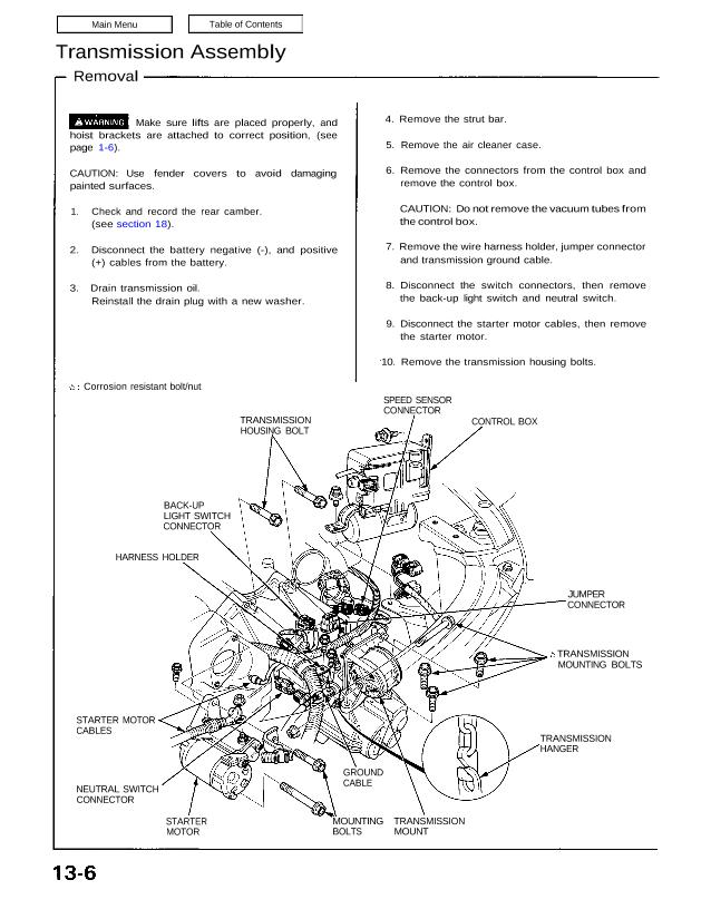
Corrosion resistant bolt/nut
TRANSMISSION
HOUSING BOLT
BACK-UP
LIGHT SWITCH
CONNECTOR
HARNESS HOLDER
STARTER MOTOR
CABLES
NEUTRAL SWITCH
CONNECTOR
STARTER
MOTOR
MOUNTING
BOLTS
TRANSMISSION
MOUNT
GROUND
CABLE
TRANSMISSION
HANGER
TRANSMISSION
MOUNTING BOLTS
JUMPER
CONNECTOR
CONTROL BOX
SPEED SENSOR
CONNECTOR
4. Remove the strut bar.
5. Remove the air cleaner case.
6. Remove the connectors from the control box and
remove the control box.
CAUTION: Do not remove the vacuum tubes from
the control box.
7. Remove the wire harness holder, jumper connector
and transmission ground cable.
8. Disconnect the switch connectors, then remove
the back-up light switch and neutral switch.
9. Disconnect the starter motor cables, then remove
the starter motor.
10. Remove the transmission housing bolts.
11. Remove the parking brake cable holders from the rear beam rod.
12. Remove the rear beam rod.
13. Remove the front exhaust pipe A.
Corrosion resistant bolt/nut
SELF-LOCKING NUT
Replace.
GASKET
Replace.
SELF LOCKING NUT
Replace.
14. Remove the parking brake cable holder and the Anti-lock Brake sensor wire clamp.
1 5. Loosen the ball joint nut, then separate the toe control arm from the knuckle using the special tool (see section 18).
16. Remove the damper fork bolt.
17. Remove the ball joint nut using the special tool and separate the lower control arm from the knuckle (see section 18).
18. Remove the right driveshaft from the intermediate shaft.
Corrosion resistant bolt/nut
SELF-LOCKING NUT
Replace.
DAMPER FORK BOLT
PARKING
BRAKE
CABLE
DRIVESHAFT
ANTI-LOCK
BRAKE
SENSOR
WIRE/CLAMP
LOWER
CONTROL
ARM CASTLE NUT
TOE CONTROL ARM
(cont’d)
CASTLE
NUT
Transmission Assembly
Removal (cont’d)
19. Remove the intermediate shaft heat cover and the intermediate shaft mounting bolts.
20. Pry the intermediate shaft out of the differential. Pull and remove it.
NOTE:
Coat all precision finished surfaces with clean engine oil or grease.
Tie plastic bags over the driveshaft ends.
INTERMEDIATE SHAFT
SUPPORT BASE
SET RING
Replace.
INTERMEDIATE SHAFT
21. Remove the parking brake cable holder and the Anti-lock Brake sensor wire clamp.
22. Scribe a reference mark on the flange of the adjusting bolt, adjusting cam and lower control arm.
23. Loosen the ball joint nut, then separate the toe control arm from the knuckle using the special tool (see section 18).
24. Remove the damper fork bolt.
25. Remove the bolts and lower control arm from the side beam.
26. Remove the left driveshaft from the differential.
27. Pry the driveshaft out of the differential. Pull and remove it.
NOTE:
Coat all precision finished surfaces with clean engine oil or grease.
Tie plastic bags over the driveshaft ends.
INTERMEDIATE SHAFT
MOUNTING BOLT
INTERMEDIATE SHAFT
HEAT COVER
DAMPER FORK BOLT TOE CONTROL ARM
LOWER CONTROL ARM
ADJUSTING
BOLT
ADJUSTING
CAM
SET RING
Replace.
28. Remove the one of the upper control arm mounting bolts.
29. Remove the lower cover, change wire bracket and upper cover.
30. Remove the shift cable and select cable.
31. Remove the slave cylinder from the transmission.
NOTE: Do not operate the clutch pedal once the slave
cylinder has been removed.
32. Remove the release fork from the clutch release hanger,
then hang the release fork on the clutch housing.
Corrosion resistant bolt/nut
UPPER CONTROL ARM DAMPER
SLAVE CYLINDER
ASSEMBLY
UPPER COVER
COTTER PIN
Replace.
SHIFT CABLE
UPPER ARM MOUNTING
BOLT
CHANGE WIRE
BRACKET
33. Remove the clutch housing cover.
34. Attach a chain hoist to the transmission hangers.
35. Place a jack under the transmission and raise the transmission just enough to take weight off mounts.
36. Remove the front engine mounting bolts on the transmission side and retighten the bolt on the engine side.
CAUTION: Loosen the front engine mounting bolt on the engine side, but do not remove it. After removing the two
bolts on the transmission side, be sure to retighten the bolt on the engine side.
37. Remove the rear transmission mounting bolts and engine stiffener.
38. Remove the transmission housing mounting bolts.
39. Pull the transmission away from the engine until it clears the mainshaft, then lower it on the transmission jack.
SELECT CABLE
LOWER COVER
RELEASE FORK
Corrosion resistant bolt/nut
REAR TRANSMISSION
MOUNT
REAR TRANSMISSION
MOUNTING BOLT
TRANSMISSION JACK
TRANSMISSION HOUSING
MOUNTING BOLT ENGINE STIFFENER
CLUTCH HOUSING
COVER
FRONT ENGINE MOUNTING
BOLT (Transmission side )
FRONT ENGINE MOUNTING
BOLT (Engine side )
TRANSMISSION HOUSING
MOUNTING BOLTS