Control Unit Input Test
Remove the glove box and disconnect the 22-P connec-
tor and 16-P connector from the control unit.
Inspect the connector terminals to be sure they are all
making good contact.
If the terminals are bent, loose, or corroded, repair
them as necessary, and recheck the system.
If the terminals look OK, make the following input
tests at the connector.
If any test indicates a problem, find and correct
the cause, then recheck the system.
If all the input tests prove OK, the control unit
must be faulty; replace it.
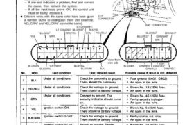
Different wires with the same color have been given
a number suffix to distinguish them (for example,
YEL/GRN1 and YEL/GRN2 are not the same).
SECURITY
CONTROL UNIT
22-P
CONNECTOR
16-P CONNECTOR
BLU/RED2
BLU/RED3
BRN
GRN/WHT
BRN/WHT
BLK/GRN GRN/RED
GRN/BLU
GRN/YEL1
GRY
GRN/YEL2
YEL
YEL/GRN2
WHT
BLU
LT GRN/RED
RED/YEL
BLU/RED1
LT GRN/WHT
GRN
BLK/YEL
YEL/BLU
View from
wire side
BLU/GRN
BLK/BRN
GRY/WHT BLU/YEL
BLU/GRN BLK
Main Menu Table of Contents
No. Wire Test condition Test: Desired result Possible cause if result is not obtained
8 BLU/RED Under all conditions. Attach to ground: The – Faulty headlight relay.
headlights should come on. ∙ Faulty headlight system.
⇁ ∙ An open in the wire.
9 RED/YEL Under all conditions. Connect to ground: The – Faulty taillight relay.
taillights should come on. – Faulty taillight system.
– An open in the wire.
10 LT GRN/ Passing switch ON. Check for voltage to ground: – Faulty passing switch.
RED There should be battery – Faulty dimmer relay.
voltage. – Faulty headlight relay.
– An open in the wire.
11 YEL/GRN2 Hood open. Check for continuity to ground: – Faulty hood switch.
There should be continuity. ∙ Misadjusted hood switch.
Hood closed. Check for continuity to ground: ∎ РОЩ ∅↾∘⊔⋅∏∁↿ ⊞⊰∘∙∏⋅
There should be no continuity. ⋅ A” open m the w’re’
12 BLU/GRN Ignition key is in the Check for continuity to ground: – Faulty ignition key switch.
ignition switch. There should be continuity. – Poor ground (G401, G402).
Ignition key is not in Check for continuity to ground: ⋅ A” open ∣∏ me w’œ’
the ignition switch. There should be no continuity.
13 BLU Engine compartment Check for continuity to ground: – Faulty engine compartment lid
lid open. There should be continuity. switch.
∙ Misadjusted engine compartment
Engine compartment Check for continuity to ground: “d SWÎÎCh-
lid closed. There should be no continuity. ‘ POO’ ground (G401: G402)—
– An open in the wire.
14 BLK/BRN Under all conditions. Check for continuity to ground: – Poor ground (G404).
or BLK/ There should be continuity. ∙ An open in the wire.
LT GRN
15 BRN/WHT Trunk key in UNLOCK. Check for continuity to ground: ∙ Faulty trunk key,
There should be continuity. ∙ Poor ground (G551).
∙ ⋀⊓ open in the wire.
16 WHT Trunk lid open. Check for continuity to ground: – Faulty trunk latch switch.
There should be continuity. – Misadjusted trunk latch switch.
Trunk lid closed. Check for continuity to ground: ⋅ P°°’ gmlfnd (6551)”
There should be no continuity. ⋅ A” Ope” ∣∏ the “те“
23-313
Security Alarm System
Control Unit Input Test (cont’d)
Main Menu
Table of Contents
Security Alarm System
Control Unit Input Test (cont’d)
No. Wire
Test condition
Test: Desired result
Possible cause if result is not obtained
17 GRN/BLU
Driver’s door open.
Driver’s door closed.
18 GRN/RED
Passenger’s door
open.
Passenger’s door clos-
ed.
Check for continuity to ground:
When the door is open, there
should be continuity.
When the door is closed, there
should be no continuity.
∙ Faulty right door switch.
– An open in the wire.
GRN/YEL‘
Driver’s door key in
UNLOCK.
GRN/YEL2
Passenger’s door key
in UNLOCK.
Check for continuity to ground:
There should be continuity.
– Faulty left or right door key switch.
– Poor ground (G401, G402).
∙ ∧⊓ open in the wire.
GFlN/WHT
Driver’s door key in
LOCK.
GRY/WHT
Passenger’s door key
in LOCK.
Check for continuity to ground:
There should be continuity, as
the door keylock is turned to
LOCK.
– Faulty left or right door key switch.
– Poor ground (G401. G402).
– An open in the wire.
BLU/REDZ
Driver’s door lock
knob in UNLOCK.
Check for continuity to ground:
There should be continuity.
– Faulty left doorvlock knob switch.
(Built into the actuator.)
– Poor ground (G401, G402).
– An open in the wire.
BLU/RED:*
Passenger’s door lock
knob in UNLOCK.
Check for continuity to ground:
There should be continuity.
– Faulty right door lock knob switch.
(Built into the actuator.)
– Poor ground (G401, G402).
– An open in the wire.
23-31 4