Control Unit Input Test
CAUTION:
AH SRS wiring harnesses are covered with yellow
outer Insulation.
Before disconnecting any part of the SRS wire
harness, install the short connectors (see page
24-10).
Replace the entire affected SRS harness assembly if
it has an open circuit or damaged wiring.
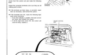
Remove the glove box, then disconnect the 14-P con-
nector from the control unit and make the following
tests.
Inspect the connector terminals to be sure they are all
making good contact.
If the terminals are bent, loose, or corroded, repair
them as necessary, and recheck the system.
If the terminals look OK, make the following input
tests at the connector.
If any test indicates a problem, find and correct
the cause, then recheck the system.
If all the input tests prove OK, the control unit
must be faulty; replace it.
SRS MAIN
HARNESS
CRUISE CONTROL
UNIT
View from
wire side
WHT GRY BLK
GRN/WHT
LT GRN/RED
LT GRN/BLX
GRN
BRN
BLU/BLK
BLU
YEL
YEL/RED
LT GRN
BLU/ORN
Main Menu Table of Contents
No, Wire Test condition Test: Desired result Possible cause if result is not obtained
1 BLK Under all conditions. Check for continuity to ground: – Poor ground (G401, 6402).
There should be continuity. – An open in the wire.
2 YEL Ignition switch ON. Check for voltage to ground: ∙ Blown No. 5 (10 A) fuse.
There should be battery ∙ ⋀⋂ open in the wire.
voltage.
3 LT GRN Ignition switch ON Check for voltage to ground: ⋅ Blown No. 5 I‘IO A) fuse.
and main switch ON. There should be battery – Faulty main switch.
voltage. ⋅ ∧⊓ open in the wire.
4 LT GRN/ RESUME button push- Ground each terminal: ∙ Blown No. 45 (20 A) fuse.
В|.К ed. Horns should sound as the – Faulty SET/RESUME switch.
5 ∟⊤ GRN, SET button pushed_ swutch IS pushed. – Faulty cable reel._
– An open in the wrre.
RED
6 BLU/ORN M/T: Clutch pedal Check for continuity to ground: ∙ Faulty or misadjusted clutch switch
pushed. There should be continuity. (MIT).
A/T: Shift lever in ∙ Faulty A/T gear position switch
2 l, 3 or D. 1А/Т).
– Poor ground (G401, G402).
∙ ∧∏ open in the wire.
7 GRN Start the engine. Check for voltage to ground: – Faulty ignition system or ECM.
There should be about 6 V. – An open in the wire.
8 YEL/RED ignition switch ON Check for voltage between the – Faulty vehicle speed sensor (VSS).
and main switch ON. YEL/RED ⊕ and BLK ⊖ ter» ∙ An open in the wire.
Raise the rear of the minals: There should be 0—5
car and rotate one V or more —0—5 \/ ог тоге
wheel slowly. repeatedly.
9 GRY Ignition switch ON, Check for voltage to ground: – Faulty brake switch.
main switch ON, and There should be О V with the – An open in the wire.
brake pedal pushed, pedal pushed and battery
then released. voltage with the pedal releas-
ed.
10 GRN/WHT Brake pedal pushed, Check for voltage to ground: – Faulty brake switch.
then released. There should be battery – An open in the wire.
voltage with the pedal pushed.
and O V with the pedal releas-
ed.
11 BLU/BLK Ignition switch ON. Attach to ground: The in— – Blown bulb.
dicator light in the gauge – Blown No. 5 (10 A) fuse.
assembly should come on. – Faulty dimming circuit in the gauge
assembly.
– An open in the wire.
12 BRN Connect battery Check the operation of the ac— – Faulty actuator.
power to the BRN ter- tuator motor: You should be – An open in the wire.
13 BLU minal and ground to able to hear the motor.
the BLU terminal.
14 WHT Connect battery Check the operation of the – Faulty actuator.
power to the WHT magnetic clutch: The clutch – An open in the wire.
terminal. should click and the output – Poor ground (G302).
linkage should be locked.
23—297