Gearbox Removal/Installation
NOTE: Before removing the steering gearbox, make
sure the front wheels are straight ahead.
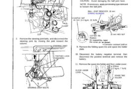
1. Remove the steering joint cover.
STEERING JOINT COVER
CLAMP
CLIP
2. Remove the steering joint bolts, and disconnect the
steering joint by moving the joint toward the
STEERING JOINT
column.
STEERING JOINT BOLTS
22 N.m (2.2 kg-m, 16 Ib-ft)
3. Lock the steering shaft with ignition key to keep
the steering shaft position.
4. Raise the car and place safety stands in the proper
locations (see secion 1).
5. Remove the front wheels.
6. Remove the cotter pin from the castel nut and
remove the nut.
7. Install the 10 mm hex nut on the ball joint. Be sure
that the 10 mm hex nut is flush with the ball joint
pin end, or the threaded section of the ball joint pin
might be damaged by the ball joint remover.
NOTE: Remove the ball joint using the Ball Joint
Remover, 28 mm (07MAC —SL00200). Refer to
page 18-21 for how to use the ball joint remover.
8. Separate the tie-rod ball joint and knuckle using the
special tool.
CAUTION: Avoid damaging the ball joint boot.
NOTE: If necessary, apply penetrating type lubricant
to loosen the ball joint.
BALL JOINT REMOVER, 28 mm
07MAC-SL00200
CASTLE NUT
44 N.m (4.4 kg-m, 32 Ib-ft)
COTTER PIN
Replace.
10 mm HEX NUT
Corrosion resistant bolt/nut
9. Remove the folding spare tire and spare tire holder
plate.
10. Disconnect the battery negative terminal, then
disconnect the positive terminal and remove the
battery.
11. Remove the spare tire holder and floor under cover.
10 N·m
SPARE TIRE
HOLDER
FLOOR UNDER
COVER
8 x 1.25 mm
BOLT
WASHERS
25 N.m
(2.5 kg-m, 18 Ib-ft)
Corrosion resistant bolt/nut
TOOTHED LOCK
WASHERS
(1.0 kg-m, 7 Ib-ft)
12. Disconnect the connectors from the EPS wire
harness.
13. Remove the ground cable by removing the EPS wire
harness stay.
EPS WIRE
HARNESS STAY
EPS WIRE HARNESS
GROUND
CABLE
FLANGE BOLT
10 N.m (1.0 kg-m, 7 Ib-ft)
14. Remove the terminal guard and ground cable.
15. Remove the terminal nuts and the wires from the
gearbox terminals.
TERMINAL NUTS
10 N.m
(1.0 kg-m, 7 Ib-ft)GROUND CABLE
NOTE: After tight-
ening the terminal
nuts, bend up the
terminal tabs
against the nuts
securely.
FLANGE BOLT
10 N.m (1.0 kg-m, 7 Ib-ft)
TERMINAL
GUARD
Corrosion resistant bolt
FLANGE BOLT
10 N·m (1.0 kg-m, 7 Ib-ft)
16. Remove the radiator pipe bracket at the front com-
partment bulkhead.
RADIATOR PIPE BRACKET
RADIATOR PIPE
17. Remove the radiator pipe bracket at the floor, and
space the radiator pipe away from and gearbox.
RADIATOR PIPE
RADIATOR PIPE
BRACKET
(cont’d)
Power Steering
Gearbox Removal/Installation (cont’d)
NOTE: Before removing the gearbox, place a stand
jack under the gearbox and front crossbeam to lightly
support them. Lower the gearbox together with the
front crossbeam.
18. Remove the flange bolts and nuts of the gearbox
and front crossbeam.
FLANGE NUTS
60 N.m (6.0 kg-m, 43 Ib-ft)
10 x 97 mm
FLANGE BOLT
(Crossbeam bracket
to Front crossbeam)
10 x 97 mm
FLANGE BOLT
(Crossbeam bracket
to Front crossbeam)
FLANGE NUT
60N.m
(6.0 kg-m,
43 Ib-ft)
10 x 97 mm
FLANGE BOLT
(Crossbeam bracket
to Front crossbeam)
LEFT SIDE:
RIGHT SIDE:
10 x 84 mm
FLANGE BOLT
60N.m
(6.0 kg-m, 43 Ib-ft)
(Gearbox to Front
crossbeam)
Corrosion resistant bolt/nut
10 x 68 mm
FLANGE BOLT
60N·m
(6.0 kg-m, 43 Ib-ft)
(Front crossbeam
to crossbeam bracket)
10 x 68 mm
FLANGE BOLT
60N·m
(6.0 kg-m, 43 Ib-ft)
(Front crossbeam to
crossbeam bracket)
10 x 97 mm
FLANGE BOLT
60N·m
(6.0 kg-m, 43 Ib-ft)
(Gearbox to Front
crossbeam)
19. Lower the gearbox and front crossbeam with care
so as not to interfere with the radiator pipe.
NOTE: The crossbeam is attached to the cross-
beam bracket with knock pins. Remove the cross-
beam by lightly taping on it with a plastic hammer,
then remove the gearbox.
LEFT CROSSBEAM BRACKET
FRONT CROSSBEAM GEARBOXASSEMBLY
20. When installing the crossbeam to the crossbeam
bracket, be sure to align the holes in the crossbeam
with the knock pins on the crossbeam bracket.
CROSSBEAM
BRACKET
KNOCK PIN
FRONT CROSSBEAM
RIGHT CROSSBEAM
BRACKET
STEERING
GEARBOX
BRACKET
CUSHION B
MOUNT BASE
FLANGE NUT
60N·m
(6.0 kg-m, 43 Ib-ft)
21. Install the gearbox in the reverse order of removal.
NOTE: When connecting the steering joint, make
sure that the cable reel of airbag system is
centered.
22. Set the steering rack in the center of its stroke.
23. Center the cable reel as follows:
Turn the steering wheel left approx. 150 degrees,
to check the cable reel position with indicator.
If the cable reel is centered, the yellow gear tooth
lines up with the alignment mark on the cover.
Return the steering wheel right approx. 150
degrees to position the steering wheel in the
straight ahead position.
YELLOW GEAR TOOTH
ALIGNMENT MARK
24. Slip the lower of the steering joint onto the pinion
shaft (line up the bolt hole with the groove around
the shaft) and loosely install the lower bolt.
NOTE:
Be sure that the lower steering joint bolt is
securely in the groove in the steering gearbox
pinion.
If the steering wheel and rack are not aligned
centered, reposition the serrations at lower side
of the steering joint.
25. Adjust the front toe after install the gearbox (see
section 18).