Under normal conditions, the EPS indicator light in the gauge assembly comes on when the ignition switch is turned
to the ON position, then goes off after the engine is started. This indicates that the bulb and its circuits are operating
correctly.
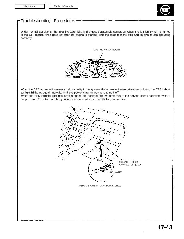
EPS INDICATOR LIGHT
When the EPS control unit senses an abnormality in the system, the control unit memorizes the problem, the EPS indica-
tor light blinks at equal intervals, and the power steering assist is turned off.
When the EPS indicator light has been reported on, connect the two terminals of the service check connector with a
jumper wire. Then turn on the ignition switch and observe the blinking frequency.
SERVICE CHECK
CONNECTOR (BLU)
GRN/WHT
SERVICE CHECK CONNECTOR (BLU)
BLU
Troubleshooting
Diagnostic Trouble Code (DTC) Display
When the service check connector terminals are connected with a jumper wire, the EPS control unit blinks the EPS indi-
cator light to indicate the DTC. The DTC is indicated by a series of long and short blinks. One long blink equals 10 short
blinks. Add the long and short blinks together to determine the DTC, then refer to the Troubleshooting Chart on page
17-51.
Example 1.3 seconds
0.28 seconds
1.3 seconds
0.36 seconds
The control unit can memorize any number of simultaneous problems. The DTC is repeated sequentially beginning with
the lowest number.
The DTC is stored in the control unit memory even when the ignition switch is turned off. After repairing the EPS system,
disconnect the CLOCK fuse in the relay box for more than 10 seconds to reset the EPS control unit memory.