Reassembly
NOTE: Coat all parts with ATF.
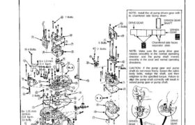
1. Reassemble the valve bodies in the following numbered sequence.
CAUTION: To prevent stripping the threads, press down on the accumulator cover while installing the bolts.
TORQUE:
6 x 1.0 mm: all bolts except : 12 N.m (1.2 kg-m, 9 Ib-ft)
6 x 1 . 0 mm: : 14 N.m (1.4 kg-m, 10 Ib-ft)
7 Bolts
2 Bolts
5 Bolts
2 Bolts4 Bolts
NOTE: Install the oil pump driven gear with
its chamfered side facing down.
NOTE: Make sure the pump drive gear
rotates smoothly in the normal operating
direction and the pump shaft moves
smoothly in the axial and normal operating
directions.
CAUTION: If the pump gear and pump
shaft do not move freely, loosen the valve
body bolts, realign the shaft, and then
retighten to the specified torque. Failure to
align the pump shaft correctly will result in
seized pump gear or pump shaft.
DRIVE
GEAR
DRIVEN
(cont’d)
8x 1.25 mm
18 N.m
(1.8 kg-m.
6 x 1.0 mm
(1.4 kg-m.
2 Bolts
13 Ib-ft)
GEAR
Chamfered side faces
separator plate.
DRIVEN
GEAR
DRIVEN GEAR
SHAFTDRIVE GEAR
NOTE: Torque bolts to 55 N.m (5.5
kg-m, 40 Ib-ft) in order of thru in
two or more steps.
NOTE: Align the control
shaft spring pin with the
groove in the transmission
housing.
6x 1.0 mm
12 N.m
(1.2 kg-m. 9 Ib-ft)
Replace.
Replace.
6 x 1.0 mm
14 N.m
(1.4 kg-m.
10 Ib-ft)
17 Bolts
10 x 1.25mm
55 N.m
(5.5 kg-m, 40 Ib-ft)
FORK BOLT HOLE
Turn valve stem so large
chamfered hole faces
fork bolt hole.
SHIFT FORK
MAINSHAFT
COUNTERSHAFT
NOTE: Install the three shafts
Transmission
Reassembly (cont’d)
2. Assemble the transmission housing in the following numbered sequence.
NOTE: See page 14-145 when installing the reverse idler gear.
SECONDARY
SHAFT
together.
(cont’d)
MAINSHAFT HOLDER
07924–PJ4010A
1ST GEAR
COLLAR
Replace.
PARKING BRAKE STOPPER
7. Install the special tool as shown, and shift to
position.
LOCK BOLT
6 x 1.0 mm
14 N·m
(1.4 kg-m, 10 Ib-ft)
ROLLER PIN
PARKING PAWL
PARKING
SHIFT ARM
PARKING PAWL SHAFT
4. Set the parking brake lever in the position, then
verify that the parking brake pawl engages the
parking gear.
5. If the pawl does not engage fully, check the parking
brake pawl stopper clearance as described on page
14-146.
6. Tighten the lock bolt and bend over the lock tab.
CAUTION: Before installing the 1st-
hold clutch O-rings, install the
1st gear collar and thrust washer.
3. Assemble the transmission in the following
numbered sequence.
NOTE: Before installing the O-rings, wrap the
shaft splines with tape to prevent damage to the O-
rings.
THRUST
WASHER
6 x 1.0 mm
14 N·m
(1.4 kg-m, 10 Ib-ft)
Transmission
Reassembly (cont’d)
8. Install a new conical spring washers and new
locknuts on each shaft.
CAUTION: Install the conical spring washers in the
direction shown.
COUNTERSHAFT LOCKNUT
Left-hand threads
CONICAL SPRING
WASHERS
NOTE: Install in this
direction.
Left-hand threads
MAINSHAFT
LOCKNUT
SECONDARY
SHAFT
LOCKNUT
9. Tighten the locknuts to specified torque.
TORQUE: 140 N.m (14.0 kg-m, 101 Ib-ft)
NOTE: Countershaft locknut has left-hand
threads.
TORQUE WRENCH
10. Stake each locknut into its shaft, using a 3.5 mm
punch.
COUNTERSHAFT
LOCKNUT
MAINSHAFT
LOCKNUT
SECONDARY
SHAFT
LOCKNUT
11. Install the feed pipes and ball bearing in the left side
cover, aligning the lugs of the 1st and 1st-hold
clutch feed pipes with the grooves of the left side
cover.
12. Install the snap ring.
BALL BEARING
mark
LINEAR SOLENOID
6 x 1.0 mm
10 N.m(1.0 kg-m, 7 Ib-ft)
MAINSHAFT SPEED SENSOR
SPEED SENSOR
COVER
LINEAR
SOLENOID
SHIM
COUNTERSHAFT
SPEED
LOCK WASHER
6 x 1.0 mm
(1.4 kg-m, 10 Ib-ft)
SPEED
SENSOR
COUNTERSHAFT
Install the countershaft speed sensor with the
countershaft speed sensor washer. The main-
shaft speed sensor has no washer.
See page 14-81 thru 82, when installing the
linear solenoid.
NOTE:
13. Install the countershaft and mainshaft speed sen-
sors, vehicle speed sensor cover and linear sole-
noid.
TORQUE: 12 N.m (1.2 kg-m, 9 Ib-ft)
CONTROL SHAFT
CHANGE SHAFT
CHANGE SHAFT CAP
6x 1.0mm
12 N.m (1.2 kg-m, 9 Ib-ft)
CONTROL
LEVER
14. Install the control lever, new lock washers, change
shaft and change shaft cap on the other end of the
control shaft. Tighten the bolts and then bend the tab
over against the bolt head.
12. Install the left side cover.
TORQUE: 12 N.m (1.2 kg-m, 9 Ib-ft)
SENSOR
WASHER
14 N.m