(cont’d)
Do not set here.Set here.
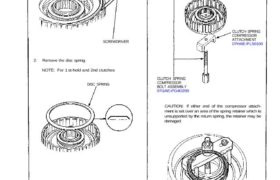
CAUTION: If either end of the compressor attach-
ment is set over an area of the spring retainer which is
unsupported by the return spring, the retainer may be
damaged.
CLUTCH SPRING
COMPRESSOR
BOLT ASSEMBLY
07GAE-PG4O200
DISC SPRING
2. Remove the disc spring.
NOTE: For 1 st-hold and 2nd clutches
SCREWDRIVER
CLUTCH SPRING
COMPRESSOR
ATTACHMENT
07HAE-PL50100
CLUTCH SPRING
COMPRESSOR
ATTACHMENT
07LAE-PX40100
3. Install the special tools as shown.1. Remove the snap rings, then remove the clutch end
plate, clutch discs and plates.
SNAP RING
Disassembly
5. Remove the circlip. Then remove the special tool,
spring retainer and return spring.
Clutch
Disassembly (cont’d)
4. Compress the clutch return spring. 6. Wrap a shop rag around the clutch drum and apply air
pressure to the oil passage to remove the piston. Place
a finger tip on the other end while applying air
pressure.
OIL PASSAGE COMPRESSED AIR
HOSE NOZZLE
OSHA-Approved 30 psi
type only.
