Self-diagnostic Procedures
I. When the Malfunction Indicator Lamp (MIL) has been reported on, do the following:
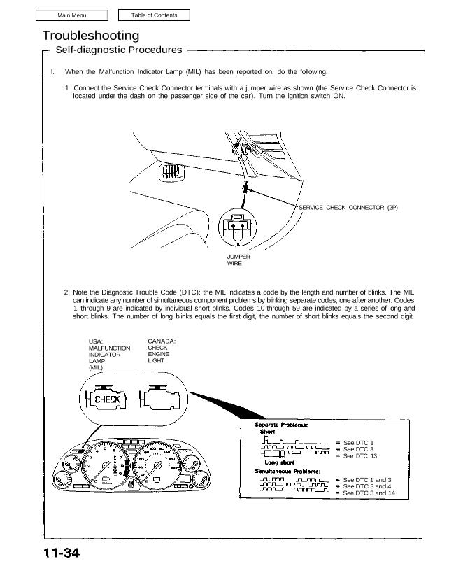
1. Connect the Service Check Connector terminals with a jumper wire as shown (the Service Check Connector is
located under the dash on the passenger side of the car). Turn the ignition switch ON.
SERVICE CHECK CONNECTOR (2P)
JUMPER
WIRE
2. Note the Diagnostic Trouble Code (DTC): the MIL indicates a code by the length and number of blinks. The MIL
can indicate any number of simultaneous component problems by blinking separate codes, one after another. Codes
1 through 9 are indicated by individual short blinks. Codes 10 through 59 are indicated by a series of long and
short blinks. The number of long blinks equals the first digit, the number of short blinks equals the second digit.
USA:
MALFUNCTION
INDICATOR
LAMP
(MIL)
CANADA:
CHECK
ENGINE
LIGHT
See DTC 1
See DTC 3
See DTC 13
See DTC 1 and 3
See DTC 3 and 4
See DTC 3 and 14
II. ENGINE CONTROL MODULE (ECM) Reset Procedure
1. Turn the ignition switch off.
2. Remove the CLOCK (7.5 A) fuse from the under-hood fuse/relay box for 10 seconds to reset ECM.
NOTE: Disconnecting the CLOCK fuse also cancels the radio preset stations and the clock setting. Make note of
the radio presets before removing the fuse so you can reset them.
III. Final Procedure (this procedure must be done after any troubleshooting)
1. Remove the Jumper Wire.
NOTE: If the Service Check Connector is jumped, the MIL will stay on.
2. Do the ECM Reset Procedure.
3. Set the radio preset stations and the clock setting.
(cont’d)
CLOCK
(7.5 A) FUSE
UNDER-HOOD
FUSE/RELAY BOX
Troubleshooting
Self-diagnostic Procedures (cont’d)
If codes other than those listed above are indicated, verify the code. If the code indicated is not listed above, replace
the ECM.
The Malfunction Indicator Lamp (MIL) may come on, indicating a system problem, when, in fact, there is a poor or
intermittent electrical connection. First, check the electrical connections, clean or repair connections if necessary.
A/T: The MIL and D indicator light may come on simultaneously when the code blinks 6, 7 and 17. Check the PGM-FI
system according to the PGM-FI system troubleshooting, then recheck the D indicator light. If it comes on, see page
14-52.
The MIL and TCS indicator light may come on simultaneously when the code blinks 3, 5, 6, 13, 15, 16, 17, 35 and
36. Check the PGM-FI system according to the PGM-FI system troubleshooting, then recheck the TCS indicator light.
If it comes on, see page 19-84.
The MIL does not come on when there is a malfunction in the A/T Fl signal. However, when the two terminals of
the service check connector are connected with a jumper wire, the MIL will indicate the codes.
PAGE
11-42
11-48
11-48
11-58
11-64
11-66
11-68
11-64
11-70
11-145
11-72
11-88
11-74
11-107
11-76
11-78
6-15
6-17
11-80
11-82
11-82
19-100
19-102
11-50
11-50
11-54
11-54
11-56
11-56
11-116
6-15
6-17
11-80
11-64
11-64
If the inspection for a particular code requires the test harness, remove the seat back panels. Unbolt the ECM. Connect
the test harness. Then check the system according to the procedure described for the appropriate code(s) listed on the
following pages.
ECM
SEAT
BACK
PANELS
DIGITAL MULTIMETER
KS–AHM–32–003
TEST HARNESS
07MAJ–PR70100
TEST HARNESS
07LAJ–PT3010A
TERMINAL LOCATION
(cont’d)
DIGITAL MULTIMETER
KS–AHM–32–003
Troubleshooting
Self-diagnostic Procedures (cont’d)
CAUTION:
Puncturing the insulation on a wire can cause poor or intermittent electrical connections.
For testing at connectors other than the test harness, bring the tester probe into contact with the terminal from the
connector side of wire harness connectors in the engine compartment. For female connectors, just touch lightly with
the tester probe and do not insert the probe.
TESTER PROBE
TERMINAL
WIRE HARNESS
RUBBER SEAL