Lighting System
Retractor Relay Test
1. Remove the retractor relay (located at the right side
of the front compartment area).
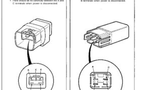
2. Check continuity at the relay terminals.
• There should be continuity between the E and F
terminals and between the B and C terminals.
• There should be continuity between the A and C
terminals when power and ground are connect-
ed to the E and F terminals.
• There should be no continuity between the A and
C terminals when power is disconnected.
Retractor Cut/Taillight Relay Test
1. Remove the retractor cut relay and taillight relay.
2. Check continuity at the relay terminals.
• There should be continuity between the C and D
terminals.
• There should be continuity between the A and B
terminals when power and ground are connect-
ed to the C and D terminals.
• There should be no continuity between the A and
B terminals when power is disconnected.
Retractor Relay Test
1. Remove the retractor relay (located at the right side
of the front compartment area).
2. Check continuity at the relay terminals.
• There should be continuity between the E and F
terminals and between the B and C terminals.
• There should be continuity between the A and C
terminals when power and ground are connect-
ed to the E and F terminals.
• There should be no continuity between the A and
C terminals when power is disconnected.
Retractor Cut/Taillight Relay Test
1. Remove the retractor cut relay and taillight relay.
2. Check continuity at the relay terminals.
• There should be continuity between the C and D
terminals.
• There should be continuity between the A and B
terminals when power and ground are connect-
ed to the C and D terminals.
• There should be no continuity between the A and
B terminals when power is disconnected.