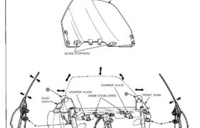
Glass Adjustment
Adjusting bolt locations.
NOTE: Take care not to damage location on the front and rear sashes.
GLASS
GLASS STOPPERS
REGULATOR ASSEMBLY
REAR GLASS GUIDE
REAR
SASH
STOPPER PLATE
INSIDE STABILIZERS
STOPPER PLATE
FRONT SASH
FRONT GLASS GUIDE
NOTE:
Place the vehicle on a firm, level surface when ad-
justing the glass.
Make sure the door position is adjusted properly
before adjusting the glass(see page 20-19 (’93-’96),
18(’91-’92)
Lower the glass fully.
1. Remove:
Door panel/Plastic cover (see pages 20-7(’93-’96),
6(’91-’92),8(’93-’96),7(’91-’92)
Door trim (see page 20-38(’93-’96),37(’91-’92)
Upper weatherstrip (see page 20-21(’93-’96)
20(’91-’92)
Front and center pillar retainers (see page 20-21 (’93-’96)
20(’91-’92)
NOTE: Check the weatherstrip for damage and de-
terioration, and replace it if necessary,
2. Remove the switch panel from the door panel (see
page 20-8(’93-’96),7(’91-’92).
3. Connect the switch panel connector to the wire
harness.
NOTE: Take care not to scratch the switch panel.
WIRE HARNESS
SWITCH
PANEL
4. Carefully close the door while holding the door
glass to prevent it from contacting the body panel.
5. Raise the glass fully.
NOTE: Check the door fit to the body opening,
6. Measure and record the clearance “H” and “B”
between the glass and body at the locations
shown.
7. Adjust the clearance as described in the steps 8
thru 9.
Measuring Points:
Section:
WINDSHIELD
“H” Clearance
GLASS
PLASTIC
GROMMET
“B” Clearance
“H” Clearance
GLASS
Section:
“B” Clearance
Section:
“H” Clearance
GLASS
“B” Clearance
Standard Clearance:
Permissible tolerance: ±2 mm (0.08 in)
Unit: mm (in)
(cont’d)
Doors
Glass Adjustment (cont’d)
“H” (See page 20-15
(’93-’96),14(’91-’92)
GLASS
a. Loosen the bolts and nuts securing the front sash,
rear sash and stopper plates, then move the front
sash all the way forward and move the rear sash
all the way backward.
NOTE: Hold the adjusting bolts with a hex
wrench when loosening the locknuts.
FRONT
SASH
LOCKNUT
REAR SASH
STOPPER PLATES
ADJUSTING
BOLT
b. Loosen the bolts securing the regulator assem-
bly, and move the regulator assembly fore or aft
to align the glass with the body at the front and
center pillars.
GLASS
Loosen.
REGULATOR ASSEMBLY
c. Loosen the nuts securing the rear glass guide, and
adjust the glass fore and aft by moving the rear
glass guide.
NOTE: Hold the adjusting bolts with a hex
wrench when loosening the locknuts.
GLASS
REAR GLASS GUIDE
ADJUSTING
BOLT
d. Repeat steps b and c until clearance “H” is
within the specified limits, then secure the regu-
lator and glass guide. Press the stopper plates
against the glass stoppers, then secure the stop-
per plates.
NOTE: Check that the stopper plates contact the
glass stoppers evenly.
STOPPER PLATE
MOUNTING
NUT
GLASS STOPPER
8. Adjust the Clearance “H” as follows:
Loosen.
Loosen.
Loosen.
Loosen.
Loosen,
LOCKNUT
9. Adjust the clearance “B” as follows:
GLASS
a. Lower the glass 10 mm (0.4 in)
b. Push the glass outward 10 mm (0.4 in), then push
the inside stabilizers against the glass lightly.
Retighten the mounting bolts securely.
NOTE: Check that the glass moves smoothly.
DOOR GLASS INSIDE
STABILIZER
MOUNTING BOLT
c. Raise the glass fully.
d. Loosen the locknuts, and turn the adjusting bolts
until the clearance “B” is within the specified
value.
LOCKNUT
ADJUSTING BOLT
REAR GLASS
GUIDE
NOTE: Turn the front and rear adjusting bolts the
same amount so as to keep the glass guide brack-
et parallel with the seating surface of the door.
After tightening the adjusting bolts, make sure
that the ends of the adjusting bolts still project
out of the locknuts.
ADJUSTING
BOLT
GLASS
CLASS GUIDE
LOCKNUT ADJUSTING
BOLT
GLASS GUIDE
BRACKET
DOOR
LOCKNUT
e. Align the front sash and rear sash with the glass
with the adjusting bolts at the bottom of the
sashes.
FRONT SASH
ADJUSTING BOLT
f. Move the glass up and down to seat it, then
measure the clearance “B” at the designated
locations (see page 20-15(’93-’96),14(’91-’92).
g. Again measure the clearance “H” to make sure
it is still within the specified limit at the designat-
ed locations.
NOTE: Repeat the above steps until the correct
clearances are obtained.
(cont’d)
(See page 20-15
(’93-’96),14(’91-’92)
NOTE: Raise the glass fully.
Adjusting
Bolt
Top Edge
of Glass
Clockwise Moved
out
Counter-
clockwise
Moved
in
LOCKNUT
GLASS
REAR SASH
GLASS
Adjusting
Bolt
Top Edge
of sash
Clockwise Moved
out
Counter-
clockwise
Moved
in
“B”
Doors
Glass Adjustment (cont’d)
10. After the clearances have been adjusted properly,
reinstall the retainers and upper weatherstrip.
11. Reinstall the door trim.
12. With the door and glass closed fully, check that the
glass contacts with the upper weatherstrip evenly.
NOTE: Measuring points are described on page
20-15(’93-’96),14(’91-’92)
Section:
WINDSHIELD FRONT PILLAR
GLASS
DOOR TRIM
Section:
UPPER
WEATHERSTRIP
Section: UPPER
WEATHERSTRIP
CENTER PILLAR
RETAINER
GLASS
DOOR TRIM
13. Check for water leaks.
NOTE: Do not use high-pressure water.
14. Install the switch panel in the door panel.
15. Install the wire harness in the door.
16. Attach the plastic cover, and install the door panel.