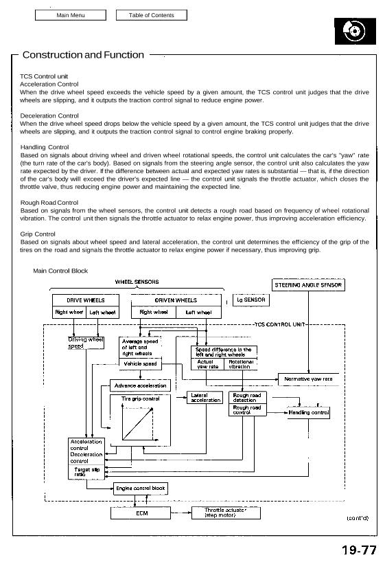
TCS Control unit
Acceleration Control
When the drive wheel speed exceeds the vehicle speed by a given amount, the TCS control unit judges that the drive
wheels are slipping, and it outputs the traction control signal to reduce engine power.
Deceleration Control
When the drive wheel speed drops below the vehicle speed by a given amount, the TCS control unit judges that the drive
wheels are slipping, and it outputs the traction control signal to control engine braking properly.
Handling Control
Based on signals about driving wheel and driven wheel rotational speeds, the control unit calculates the car’s “yaw” rate
(the turn rate of the car’s body). Based on signals from the steering angle sensor, the control unit also calculates the yaw
rate expected by the driver. If the difference between actual and expected yaw rates is substantial — that is, if the direction
of the car’s body will exceed the driver’s expected line — the control unit signals the throttle actuator, which closes the
throttle valve, thus reducing engine power and maintaining the expected line.
Rough Road Control
Based on signals from the wheel sensors, the control unit detects a rough road based on frequency of wheel rotational
vibration. The control unit then signals the throttle actuator to relax engine power, thus improving acceleration efficiency.
Grip Control
Based on signals about wheel speed and lateral acceleration, the control unit determines the efficiency of the grip of the
tires on the road and signals the throttle actuator to relax engine power if necessary, thus improving grip.
Main Control Block
System Description
Construction and Function
Fail-Safe Function
If the control unit detects an abnormality, it shuts the
traction control system off and causes the TCS indicator
light to come on. However if the abnormality is detected
while the TCS is activated, the control unit first estab-
lishes the appropriate wheel spin velocity, then shuts
the system down, thus preventing excessive wheel spin.
Self-Diagnosis Function
If the control unit detects an abnormality, it records a
Diagnostic Trouble Code (DTC) which can be used to
diagnose the problem. The DTC is shown at the TCS
indicator light when the Service Check connector termi-
nals are connected with the SCS service connector.
Steering Angle Detection
Steering angle is detected by the steering angle sensor,
located on the steering column. The sensor uses two
magneto-resistor (MR) elements to determine steering
angle and direction of rotation. When the driver turns
the steering wheel, a magnet in the steering shaft gener-
ates waves in the “MR” elements. These waves are
amplified and converted into signals which the control
unit can interpret as angle and direction of turn.
MR ELEMENT
TCS INDICATOR LIGHT
MR
ELEMENT
Vehicle Speed Detection
Wheel rotation speed is detected by the wheel sensors,
located at each wheel. The signals are sent to the con-
trol unit, which compares each wheel’s speed and deter-
mines whether traction control is required.
GEAR PULSER
WHEEL SENSOR
Lateral Acceleration Detection
Lateral acceleration is detected by the lateral accelera-
tion (Lg) sensor located under the rear center trim panel.
The Lg sensor varies the output voltage in accordance
with the left or right side acceleration and sends it to the
TCS control unit as a lateral acceleration signal.
Lg SENSOR
90 degrees
VOLTAGE
RIGHT SIDE ACCELERATION
OUTPUT CHARACTERISTIC
LEFT
TURN
RIGHT
TURN
LATERAL
ACCELERATION