Reassembly
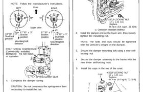
1. Install the damper unit on a spring compressor.
2. Assemble the damper in reverse order of removal
except the damper mounting washer and self-
locking nut.
NOTE: Align the bottom of damper spring and spr-
ing lower seat as shown.
3. Position the damper mounting base on the damper
unit as shown.
NOTE: Follow the manufacturer’s instructions.
LEFT Front RIGHT
Upper view
17°30′ ± 3°
Bracket
position
18°30′ ± 3°
Stud bolt
position
17°30′ ± 3°
Bracket
position
Mounting bolt
direction
STRUT SPRING COMPRESSOR:
(Commercially available)
BRANICK® T/N MST-580A
or equivalent
18°30″ ± 3°
Stud bolt
position
Mounting bolt
direction
SPRING LOWER SEAT
4. Compress the damper spring.
CAUTION: Do not compress the spring more than
necessary to install the nut.
5. Install the damper mount washer and a new self-
locking nut.
6. Hold the damper shaft, then tighten the self-locking
nut.
SELF-LOCKING NUT
10 x 1.25 mm
Replace.
30 N-m (3.0 kg-m, 22 Ib-ft)
Installation
1. Reposition the damper on the frame with the weld-
ed nut of the hose bracket facing outside as
shown.
DAMPER
MOUNTING BOLT
BRAKE HOSE MOUNTING BOLT
22 N-m (2.2 kg-m. 16 Ib-ft)
SELF-LOCKING NUT
12 x 1.25 mm
Replace.
95 N-m (9.5 kg-m. 69 Ib-ft)
Corrosion resistant bolt/nut
2. Install the damper end on the lower arm, then loosely
tighten the mounting nut.
NOTE: The bolts and nuts should be tightened
with the vehicle’s weight on the damper.
3. Secure the damper mounting bolt using a new self-
locking nut.
4. Secure the damper assembly to the frame with the
new three self-locking nuts.
5. Install the caps in the top of the cowl.
CAP
SELF-LOCKING NUT
10 x 1.25 mm
Replace.
44 N-m (4.4 kg-m, 32 Ib-ft)
Corrosion resistant bolt/nut
6. Install the brake hose mounting bolt.
DAMPER
MOUNTING WASHER