Installation
SRS components are located in this area. Review the
SRS component locations, precautions, and procedures
in the SRS section 24 before performing repairs or ser-
vice.
1. Slip the lower end of the steering joint onto the pin-
ion shaft.
2. Reposition the column assembly on the hanger
bracket, and loosely tighten with 8 mm flange nuts.
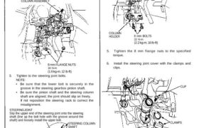
COLUMN ASSEMBLY
8 mm FLANGE NUTS
16 N-m
(1.6 kg-m, 12 Ib-ft)
3. Tighten to the steering joint bolts.
NOTE:
• Be sure that the lower bolt is securely in the
groove in the steering gearbox pinion shaft.
• Be sure the pinion shaft and the steering column
shaft are aligned; the joint should slip on freely.
If not reposition the steering rack to correct the
misalignment.
STEERING JOINT
Slip the upper end of the steering joint onto the steering
shaft (line up the bolt hole with the groove around the
shaft) and loosely install the upper bolt.
STEERING COLUMN
SHAFT
Pull down while
tightening bolt.
Bolt must line up with flat
on shaft.
STEERING GEARBOX
PINION SHAFT
TOOTHED LOCK
WASHERS
STEERING JOINT BOLTS
22 N-m (2.2 kg-m, 16 Ib-ft)
4. Install the column holder with the 8 mm bolts.
COLUMN
HOLDER 8 mm BOLTS
22 N-m
(2.2 kg-m, 16 Ib-ft)
5. Tighten the 8 mm flange nuts to the specified
torque.
6. Install the steering joint cover with the clamps and
clips.
CLIP
CLAMPS
STEERING JOINT COVER
7. Install the combination switch assembly over the
column shaft.
COMBINATION SWITCH
ASSEMBLY
COLUMN SHAFT
8. Reconnect TCS sensor connector.
TCS SENSOR CONNECTOR
(GREEN)
TCS SENSOR
9. Install the column covers.
NOTE: Be careful not to damage the column covers.
UPPER COLUMN COVER
LOWER
COLUMN
COVER
10. Insert the cable reel 3P connector through the col-
umn lower panel, and attach it to the column lower
panel with the connector holder. Then connect the
SRS main harness and cable reel 3P connector.
11. Install the column lower panel.
COLUMN
LOWER
PANEL
SRS MAIN
HARNESS
CONNECTOR
HOLDER
CABLE REEL 3P
CONNECTOR
Steering Column
Installation
12. Install the dashboard brace and dashboard lower
pad.
13. Connect the foot well light harness and light-on
warning chime to the dashboard lower panel, then
install the dashboard lower panel.
DASHBOARD BRACE
DASHBOARD LOWER
PAD
DASHBOARD
LOWER PANEL
14. Install the steering wheel and airbag assembly to
the column (see page 17-45).